Week 9 - Challenge 1 - Base Bracket Design
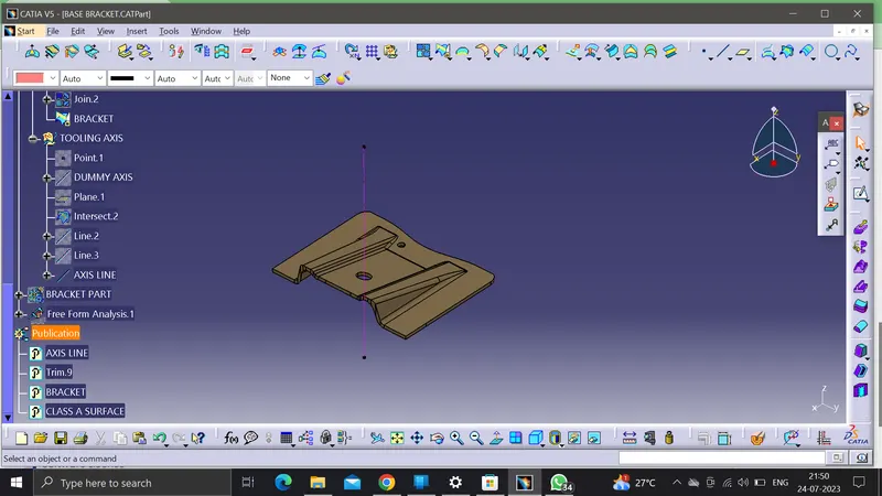
TOOLING AXIS
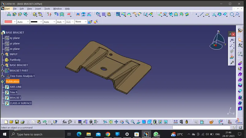
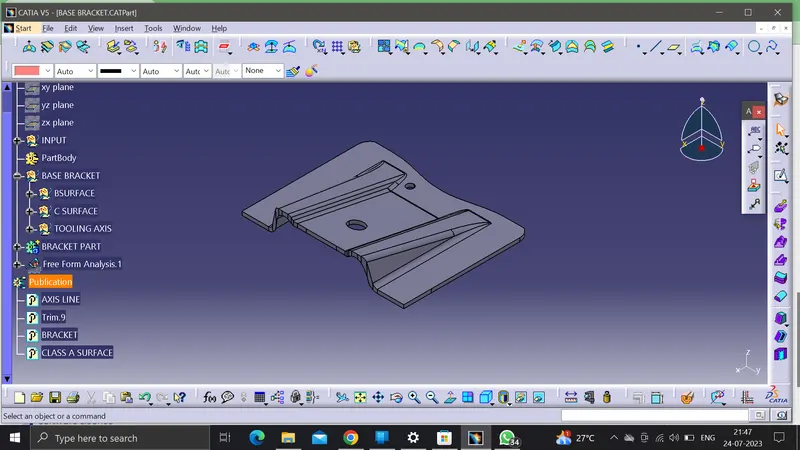
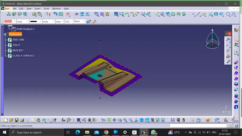
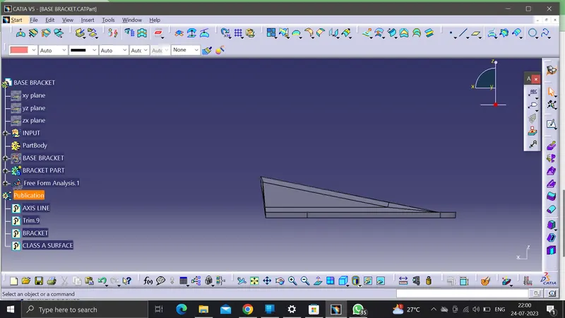
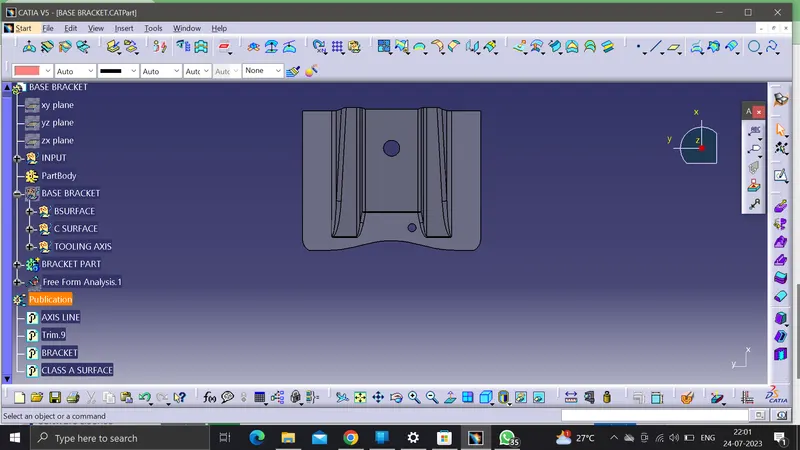
- After taking a close look on the Class A surface, it was understood that the flat surface as well as the holes were lying in the xy plane. Therefore a dummy tooling axis was made perpendicular to it.
- Then the inclined surfaces were used to project as lines.
- The tooling axis was made from the bisector of these 2 inclined lines
- Since there were not any inclinations in the x direction that could impede the injection process, it was not used for making the tooling axis in this case.
- Had there been such surfaces the lines projected from those inclined surfaces would be used to create another bisector which is the tool clearing axis in x direction.
- The two axes thus formed are then bisected again to create the actual tooling axis.
DRAFTING
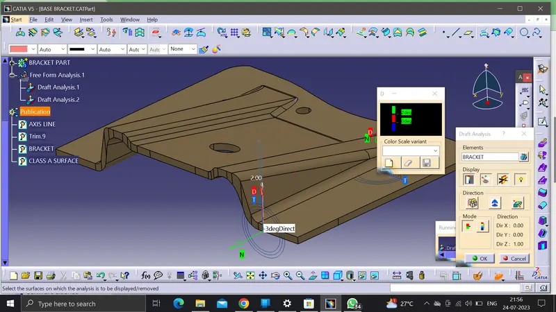
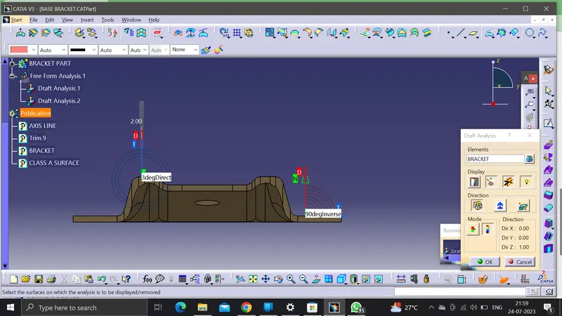
- The Class A surface is checked for the angle of draft provided through draft analysis.
- First the compass is used to define the drafting direction.
- Then after selecting the surface, the color grade can be used to identify the angle of draft in a nutshell through the colors.
- Furthermore, the analysis under running mode can be used to check each surfaces manually.
3D MODEL