Week 9 - Challenge 1 - Base Bracket Design
AIM:Create the Base Bracket Plastic component through the given Class-A surface and A detailed report should be done explaining the draft analysis and the tooling axis creation.
INTRODUCTION:
The main objective of this challenge is to create the Base Bracket Plastic component through the above-given Class-A surface, by giving the 'Tooling axis' and 'Draft analysis' to the class-A surface of the base bracket.
OBJECTIVE
1.Tooling Axis
2.Draft Analysis
3.Creation of Class B & C Surface with A
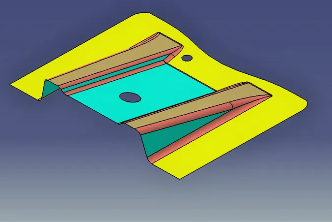
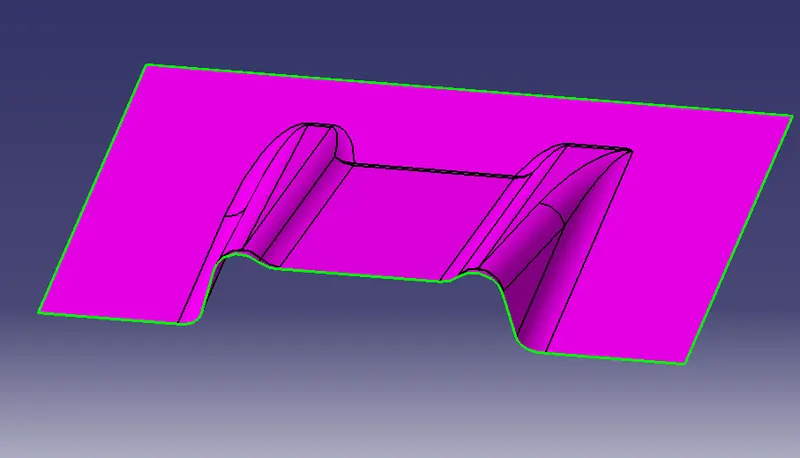
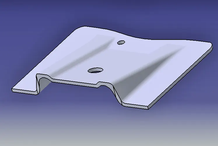
- CLASS A SURFACE
Following surface is given as the input for the component creation.
TOOLING AXIS:
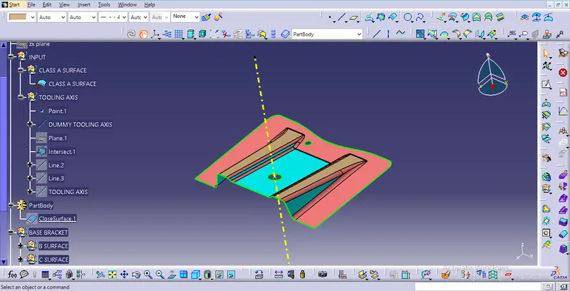
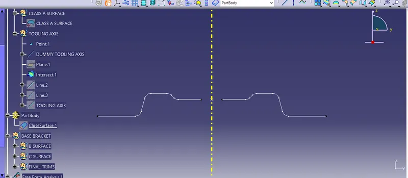
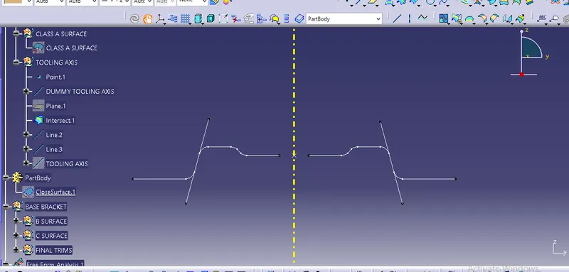
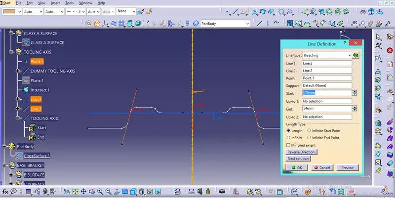
For the Creation of Tooling Axis observe the Class A surface and Creating the dummy Tooling axis on Z -axis from the middle hole of the class A.
DRAFT ANALYSIS:
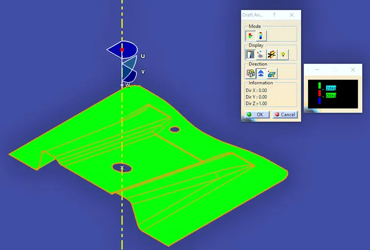
To perform draft analysis, click on Insert >>Analysis >> Feature Draft Analysis
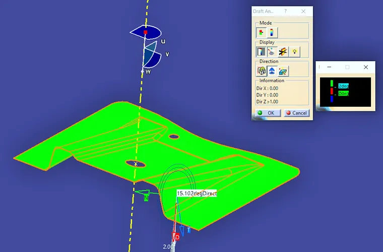
- Align the tooling axis with the compass.
- Click on the surface and see that the surface is within the permissible limit of the draft values.
- The surface should be green and in the column proper value (3deg) should be inserted.
- CLASS B SURFACE
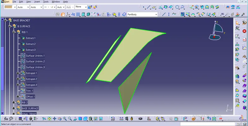
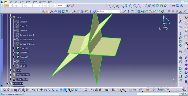
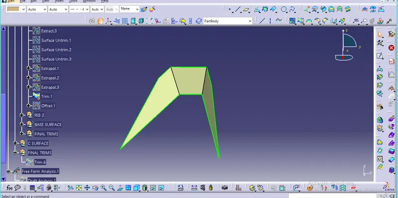
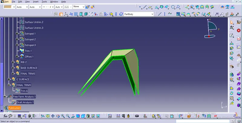
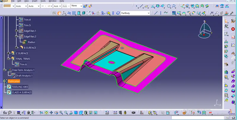
Creation of Class B from Class A includes 5 operations,
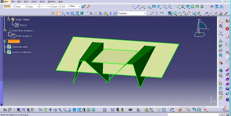
First Extract two ribs and then Extract Base surface.
- Extract the surface.
- Un-trim the surface.
- Extrapolate it.
- Trim
- Offset it by 2.5mm i.e. thickness.
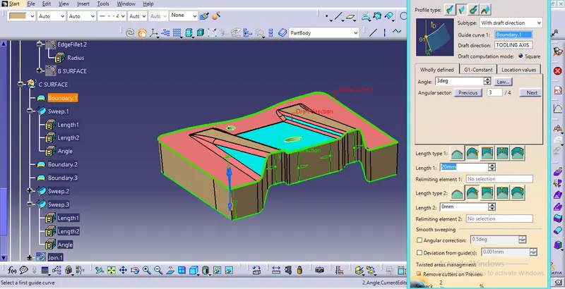
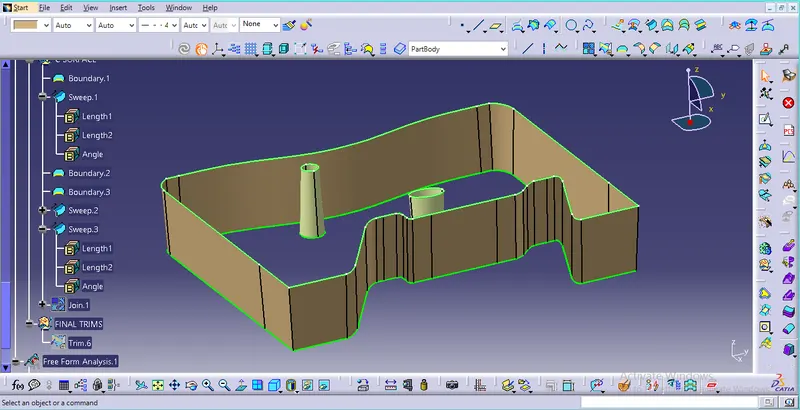
- CLASS C SURFACE
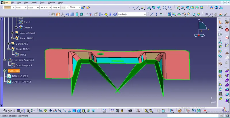
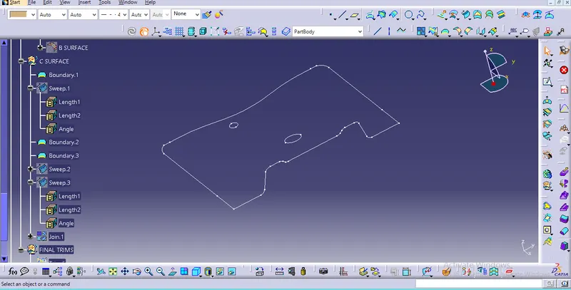
- Extract the boundary of the class-A surface.
- Extract the boundary of the holes on the class-A surface.
- Use sweep command on the boundaries one by one to get the class-C surface.
- FINAL BASE BRACKET
Join the class-A and class-C surfaces together and Trim it.
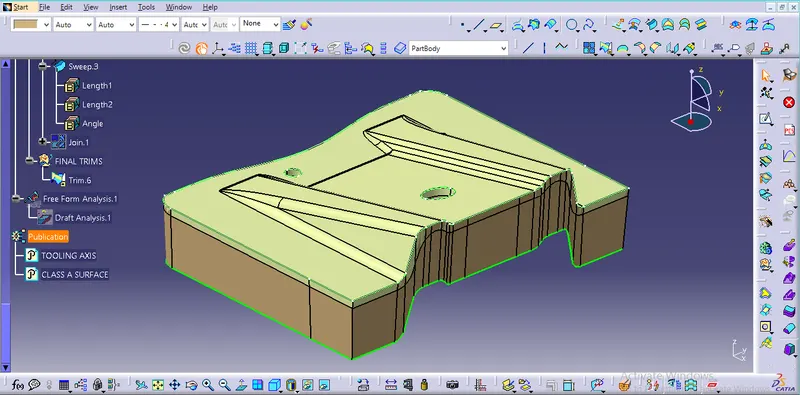
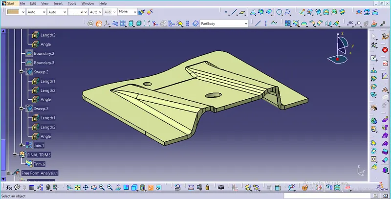
Go to part design and close the model.
RESULT:Thus the Base Bracket Design completed successfully.