Week 9 - Challenge 1 - Base Bracket Design
Aim
Create the Base Bracket Plastic component through the given Class-A surface.
Create the tooling axis for the given Class-A Surface should be created meeting the requirements of the draft angle and at the end perform the Draft analysis on the model.
Objectives:
- Creation of Tooling Axis.
- Creation of Class B and Class C surface.
- All the sketches should be created under the Geometrical set.
- Use the Close Surface feature to make a solid body from the surface.
- Publications: Use the publication option and publish the below.
Introduction:
In this challenge designing a base bracket using given class A surface. The approach includes creation of Class B surface keeping 2.5 mm thickness in mind for the complete component. The design also included Class C creation from the given parent surface.
Class A surface
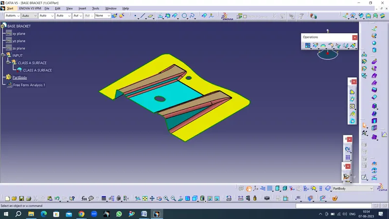
To continue with the design process first we need to find out the tooling axis for the surface and check for all the drafts using Draft Analysis
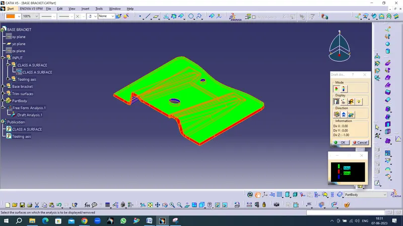
Draft Analysis for Surface A:
The analysis is done for 3degree draft. So as can be seen all the surfaces are more than 3deg.
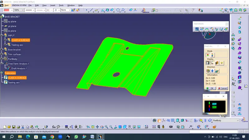
Creating of Tooling Axis:
1. Doing the boundry check to ensure whether the given class-A surface is continuous or not. It seems there is not any discontinuous boundary.
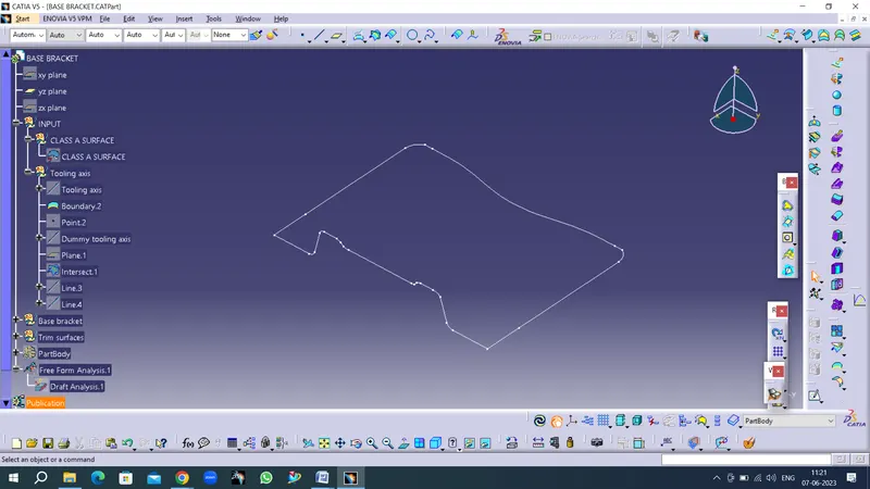
2. This is the surface and YZ plane intersection boundary line. The nearest parallel surface to assumed drawing direction is chosen for bisecting.
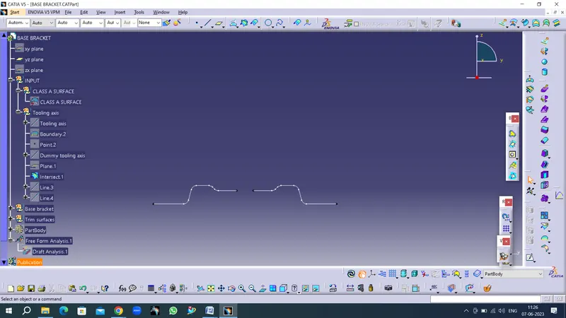
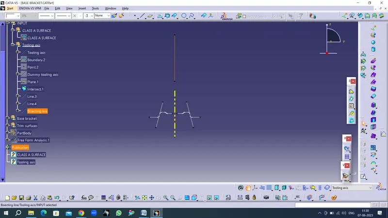
Here, Line shown in dotted yellow is the tooling axis.
Creation of Class B:
-
RIB CREATION
- Bringing in the class-A surface.
- Extracting the rib surface.
- Un-trim the extracted surface.
- Extrapolate the un-trimmed surface.
- Trim the surface as per required shape.
- Repeat step 2, 3 and 4 for the next rib surface.
- Offset the created rib surfaces for 2.5mm. ( CLASS-B SURFACE)
Rib surfaces
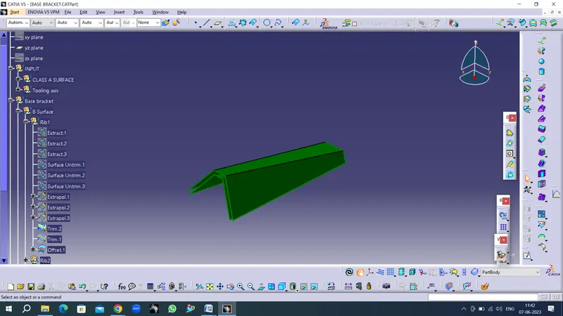
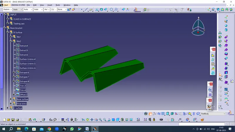
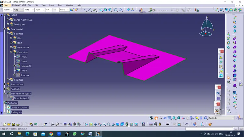
MIDDLE FLAT CONNECTING SURFACE
- Extract the middle flat connecting surface from class-A.
- Un-trim the extracted surface.
- Extrapolate the un-trimmed surface.
- Offset the extrapolated untrimmed surface for 2.5mm.
- Trim the surfaces. (CLASS-B SURFACE)
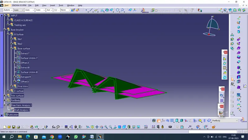
CREATION OF BASE SURFACE
- Extract the base surface from class-A surface.
- Un-trim the base surface.
- Extrapolate the base surface.
- Offset the base surface for 2.5mm
- Trim the base surface from the middle surface which is already created.
JOIN
- Join all the class-B surfaces to make as one unit.
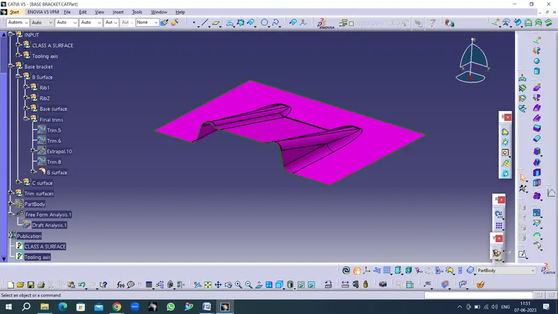
FILLET
- Since the class-B surface is 2.5mm downwards to the class-A surface need to add this offset distance with the filleting radius observed from the class-A surface.
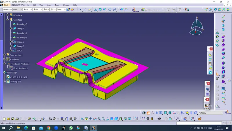
CLASS-C SURFACE
This the connecting surface of class-A and class-B surfaces.
- Create the boundary of class-A surface using boundary command.
- Use sweep command to generate class-C surface along the draft direction with 3 degrees drafting angle with respect to the tooling axis.
- Extrapolate the hole features from class-A surface and trim them.
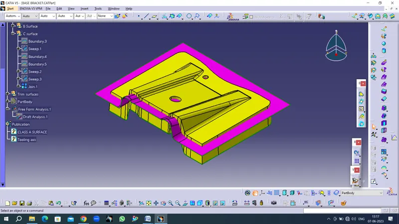
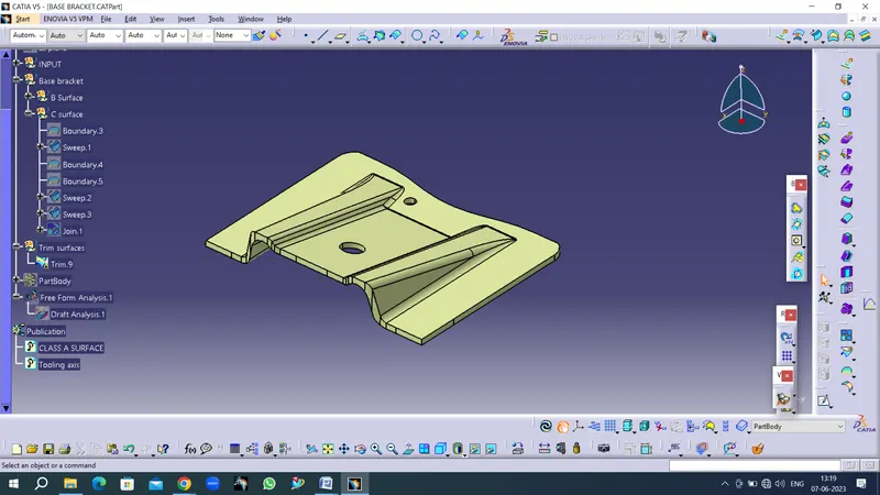
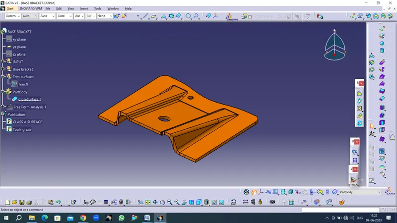
CLOSED SURFACE
- Publish class-A, class-B, class-C surfaces and tooling axis.
- Join all the surface together.
- Create closed surface.
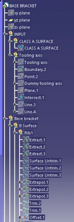
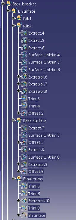
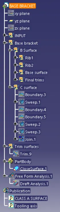
Tree Structure
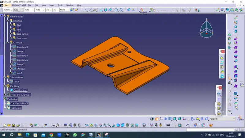
Isometric view
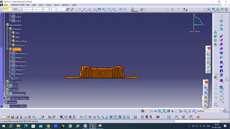
Front view
TOp view
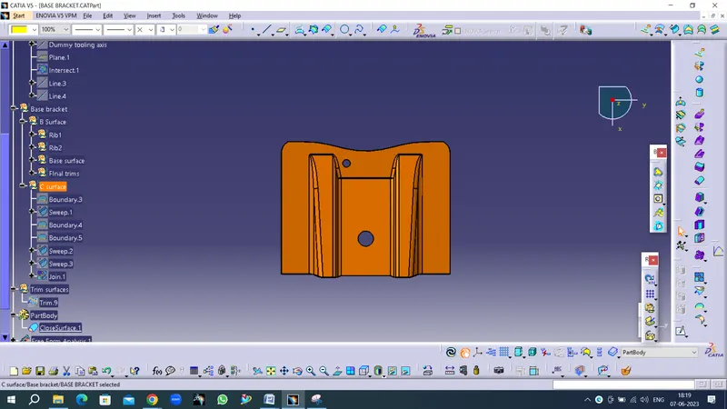
Side view
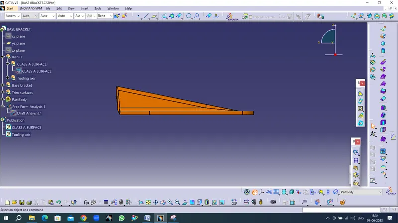
Draft analysis of final plastic component
CONCLUSION
Hence the plastic component is created from class-A surface and draft analysis is done.