Week 9 - Challenge 1 - Base Bracket Design
ANSWER:
BASE BRACKET DESIGN
AIM:
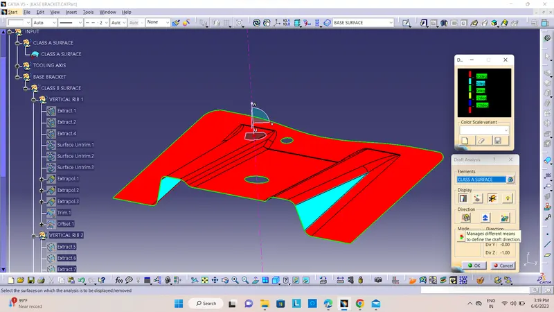
To create the Base Bracket Plastic component through the given Class-A surface by creating a tooling axis meeting the requirements of the draft angle and to perform the Draft Analysis on the solid model at the end.
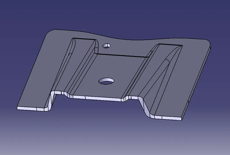
Given Class A surface
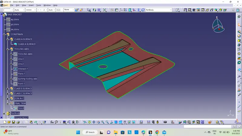
TOOLING AXIS:
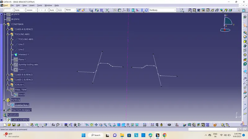
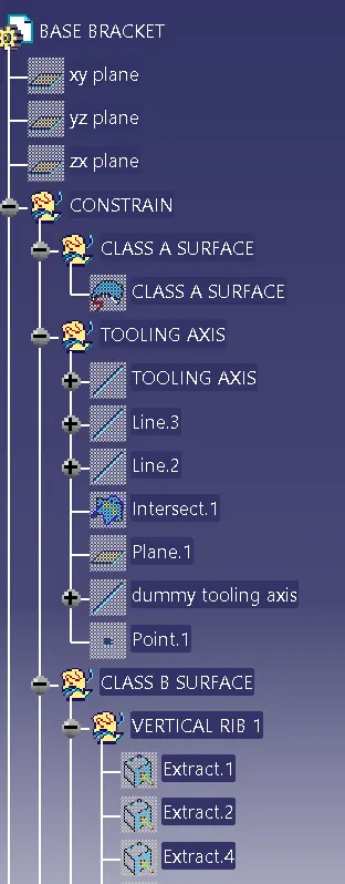
Tooling axis or Molding axis is the direction in which the core and cavity opens. It is basically the direction that the mold pulls apart. Creating a tooling axis is necessary to provide draft angle and analyze them. The tooling axis is created using Bisecting method.
BISECTING METHOD:
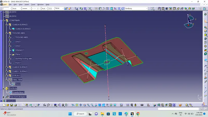
To decide the Tooling axis, it is made sure that the component is clearing the tooling axis in the given specific direction. The first step is to visually check the component for the best tooling direction in all three x, y and z directions. In the given Class A surface it is found that the best tooling direction is Z axis as the holes present on the surface cannot be cleared in either X or Y directions with minimum tooling. So Z direction is chosen for Tooling axis.
After the selection of direction, a dummy tooling axis is created in that direction for reference.
CLASS B SURFACE
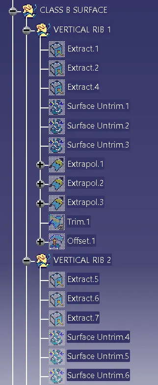
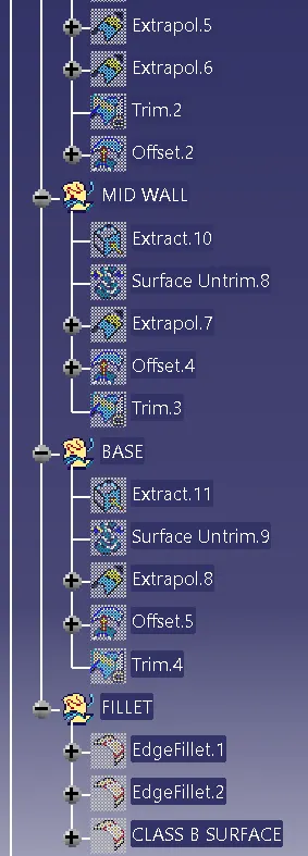
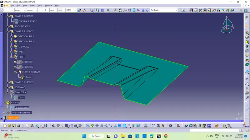
To create Class B surfaces, we first extracted the surfaces from Class A and then untrimmed them to obtain the original parent surface. The next step was to offset these surfaces to the required thickness and then trim them into the desired shape. Finally, we added the necessary fillets to achieve the desired result.
CLASS C SURFACE
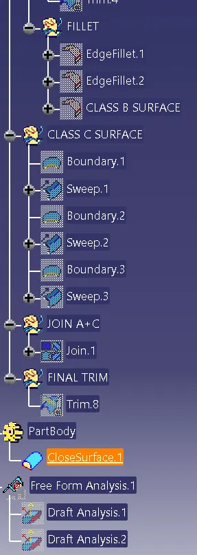
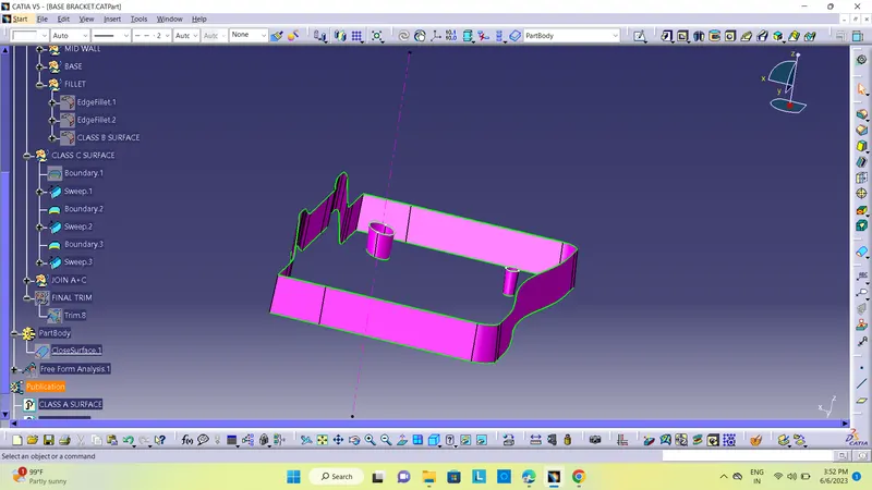
A Class C surface is a combination of Class A, Class B, and Class C surfaces used to create a solid body. To make a Class C surface, I utilized the sweep command and selected the outer boundary of the Class A surface. I then used the 'line' command under the 'profile' block and chose the subtype 'with draft direction.' After selecting the tooling axis and giving a 3-degree angle, I swept the direction inside down arrow, with the Class B surface under the Class A surface. This process was repeated for the two circles on the Class A surface. Finally, I joined all the sweeped surfaces using the 'join' command and trimmed the Class A, Class B, and Class C surfaces to create a closed surface and ultimately a solid body.
JOINING CLASS A + CLASS C
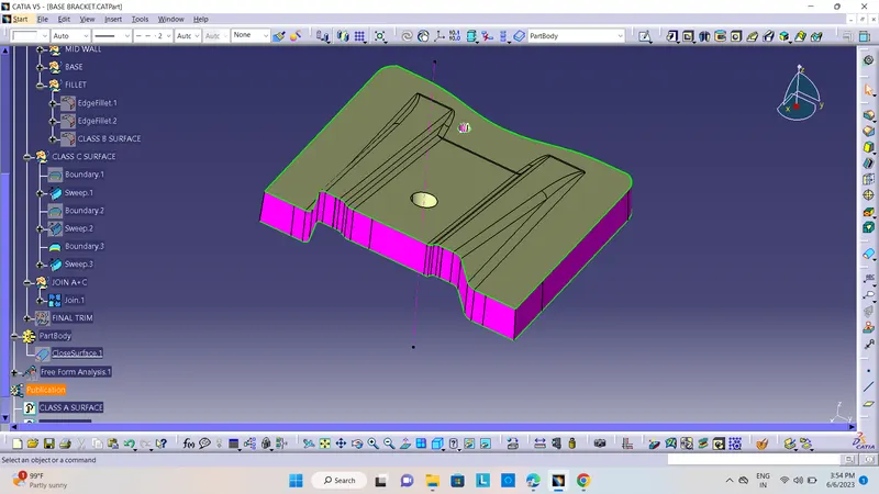
JOINING CLASS A + CLASS C + CLASS B
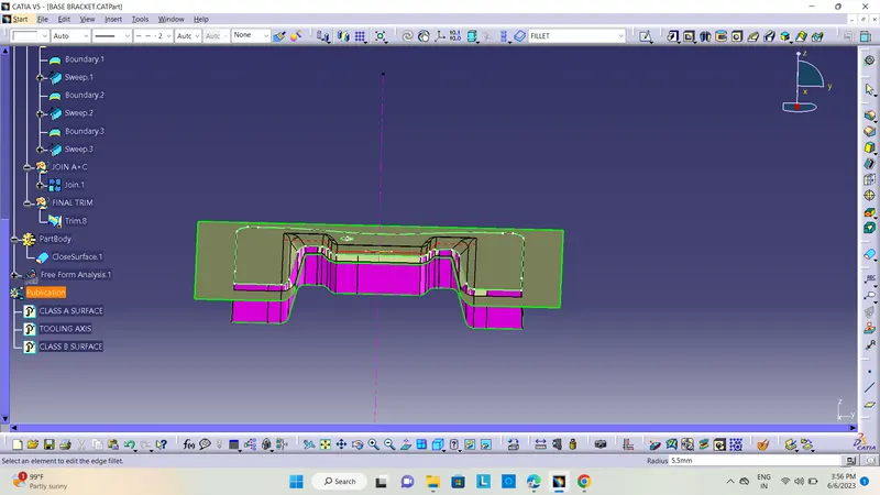
FINAL TRIM
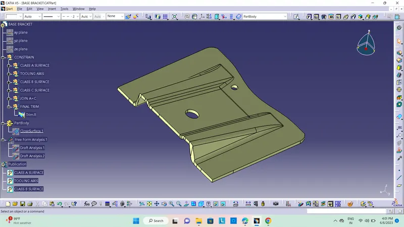
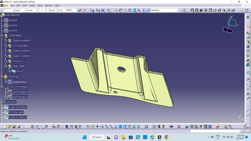
FINAL REPRESENTATION OF BASE BRACKET DESIGN
FINAL DRAFT ANALYSIS
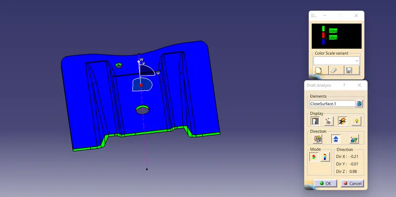
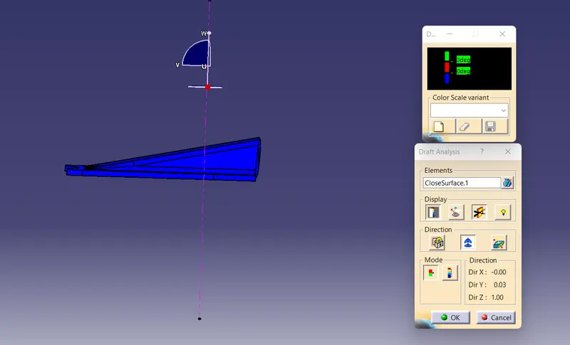
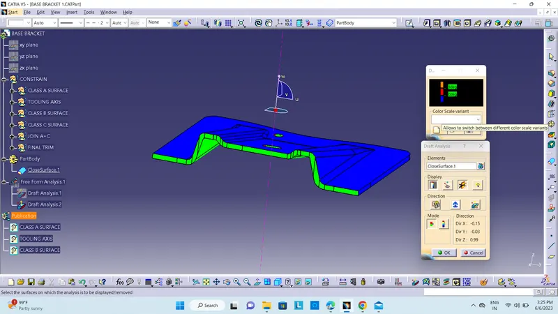
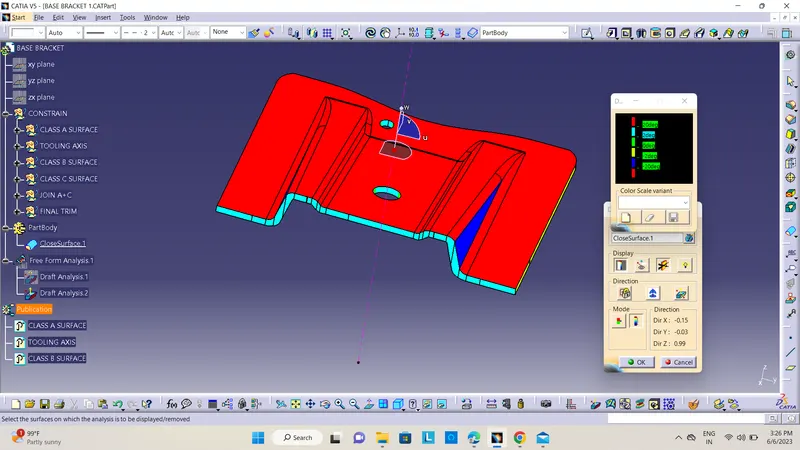
class A surface draft
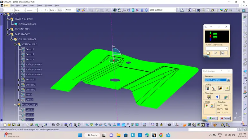
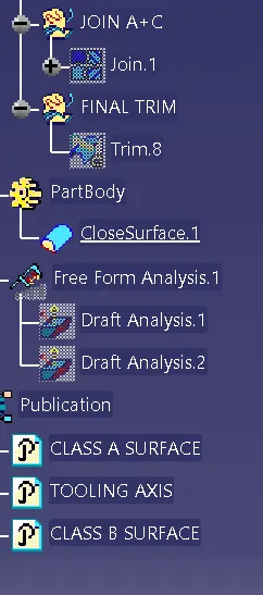
EXPANDED TREE STRUCTURE: