Week 9 - Challenge 1 - Base Bracket Design
Objective: Create the Base Bracket Plastic component through the given Class-A surface.
Given Class A Surface
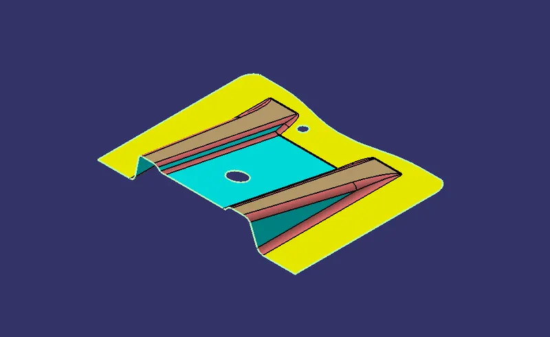
PROCEDURE:
A) TOOLING AXIS CREATION:
- Create a point on class A surface with the aim to move the main tool for component creation .
- Mask an axis over the point created with the same directions as the main axis
 .
. - Using Intersect command from Generative Shape design select the YZ plane as the first element and the class A surface as the second element
 .
. - After creating the intersecting lines select the Line command and join the vertices which show the most possible +ve draft angle manufacturable

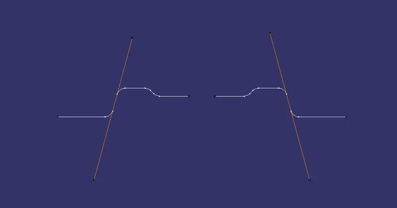 .
.
- After creating these two lines use the bisect option from the line command.
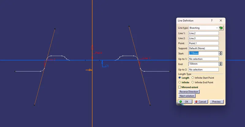
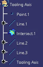
- The tooling axis for manufacturing the part is created.
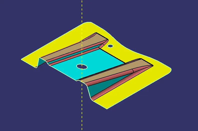
Tree Structure for Tooling Axis
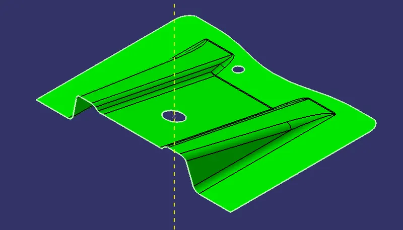
B) Draft Analysis of Class A Surface:
- After Tooling Axis Select the Feature Draft Analysis option from the Insert > Analysis > Feature Draft Analysis Option
 .
.
- Select the element to analyze.
- Next click on Use the compass to define the new current draft direction option and make it align with the tooling axis by dragging it to the axis

- Next use the lock option
 to lock the compass to the tooling Axis.
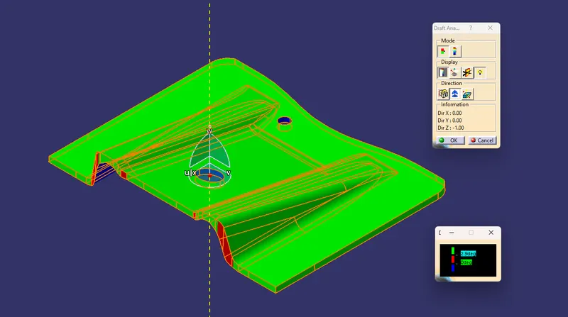
- If the color appears blue just click the invert option on the right side of the draft direction axis button

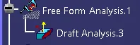
Tree Structure For Draft Analysis
C ) Creating Class B Surface Creation:
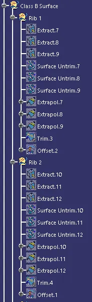
- Using the Extract option select the first set of ribs from the Class A surface
 .
.
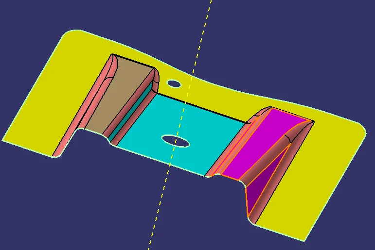
- use extract similarly for other irb, middle plate, base.
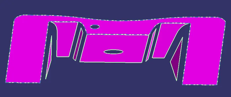
- then use untrim option
 to remove trims and get original shape.
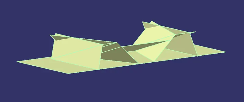
- Then use the extrapolate option
 to get rid of any gaps between the intersectios.
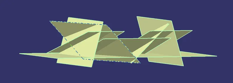
- then give offsets of 2.5 mm for desired thickness.
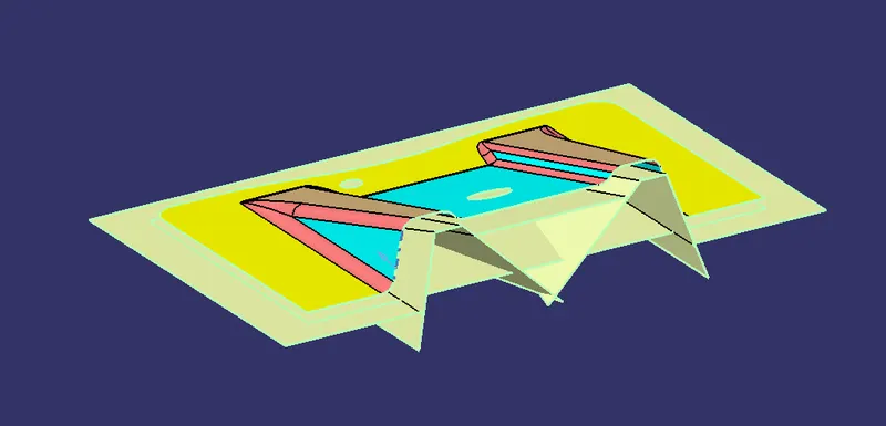
- then use the trim option to get the required shape.
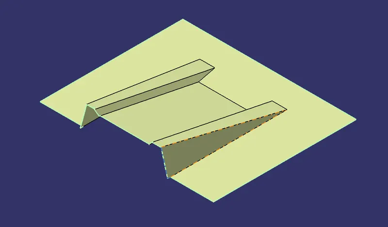
- after this use the fillet option to give the fillets as class A. As we are giving offset we have to give radius+thickknees for fillet input.
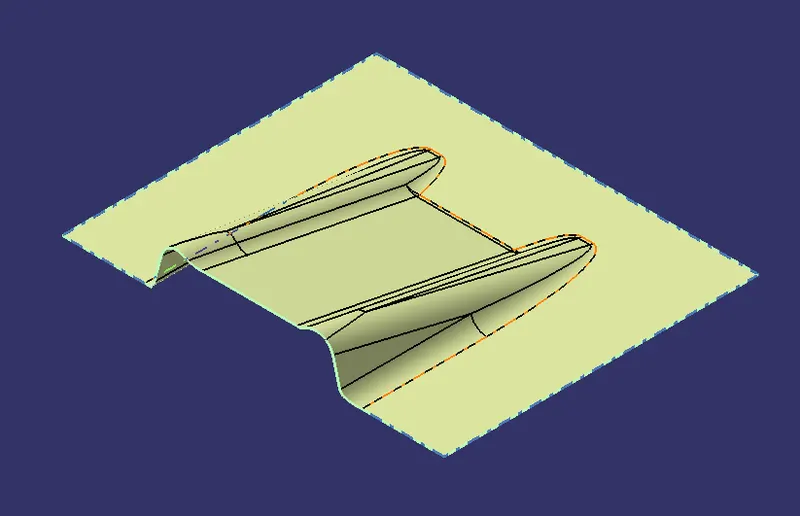
D ) Class C Surface Creation:
- Use the boundary command
 to get the edge of the class A.
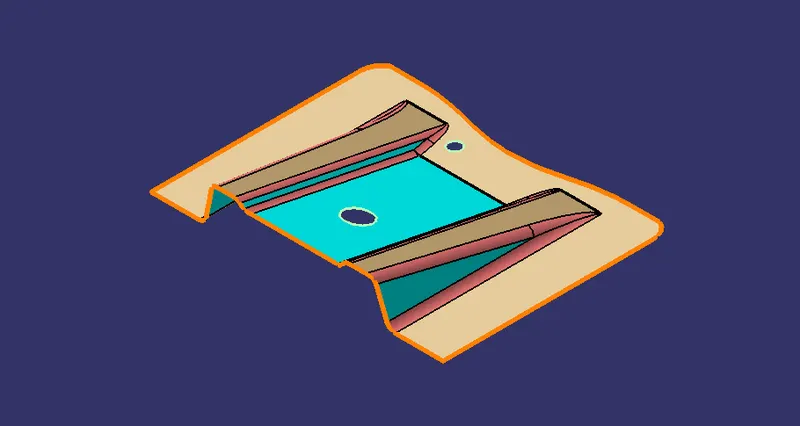
- use the sweep command
 and give the boundary, tooling axis and draft angle as input to get the Class C Surface.
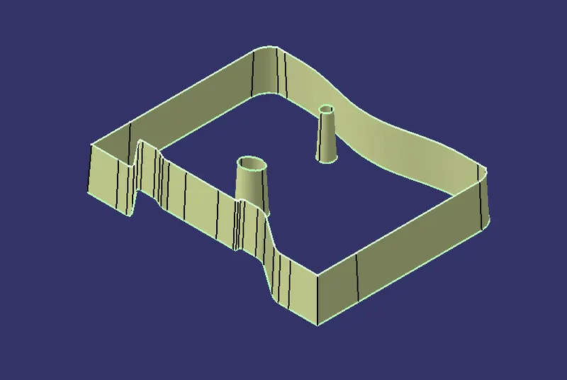
- Use the join command
 to join the class C & Class A Surfaces.
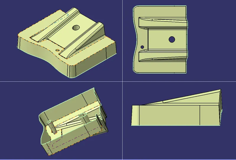
E ) Final Creation:
- Use the Joined Surface & Class B Surface and make a trim.
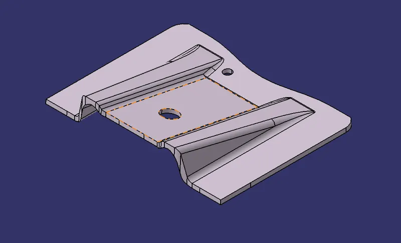
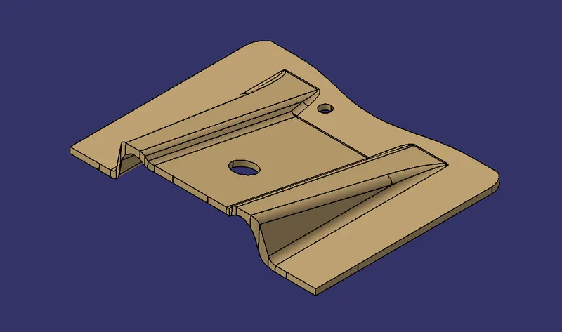
F ) Closed Surface:
- Go to Part > Body > Closed Surface command
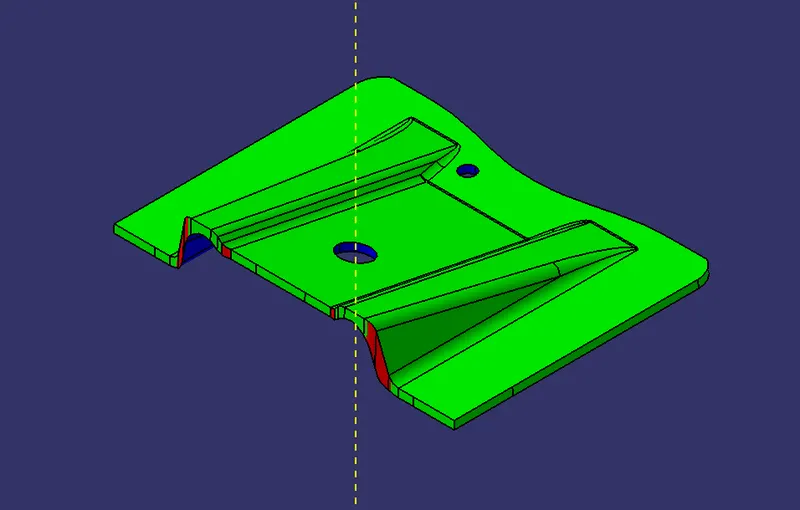
 and we have a final solid part.
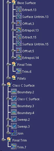
Tree Structure For Class b & C creation:
Draft Analysis For Class A Surface
Draft Analysis For Final Closed Surface
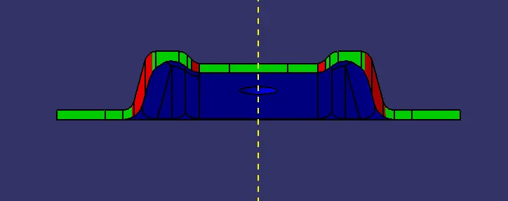
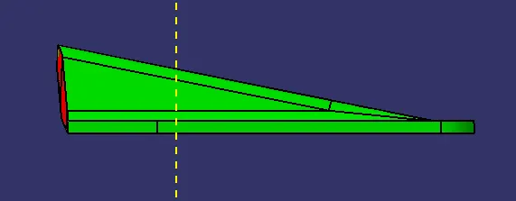
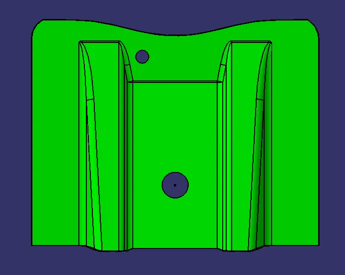
Views
Isometric
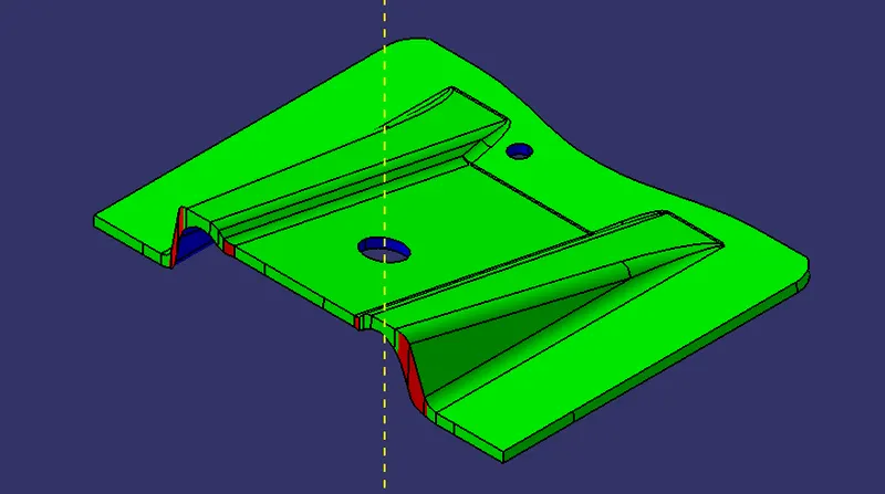
Fornt
Side
Top
Conclusion : Created the plastic component in Catia V5 using the given Class A Surface.
- Created the tooling axis.
- Ceated the Class B Surface
- Created the Class C Surface
- Created the Closed Surface from Surface geometry.
- Did the Draft Analysis