Week 9 - Challenge 1 - Base Bracket Design
AIM
To Create the Base Bracket Plastic component through the given Class-A surface. To begin with, the tooling axis for the given Class-A Surface should be created meeting the requirements of the draft angle and at the end perform the Draft analysis on the model.
GIVEN
Thickness of Plastic Part - 2.5 mm
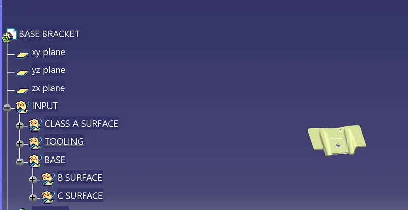
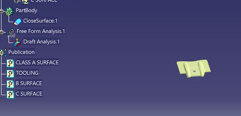
TREE STRUCTURE
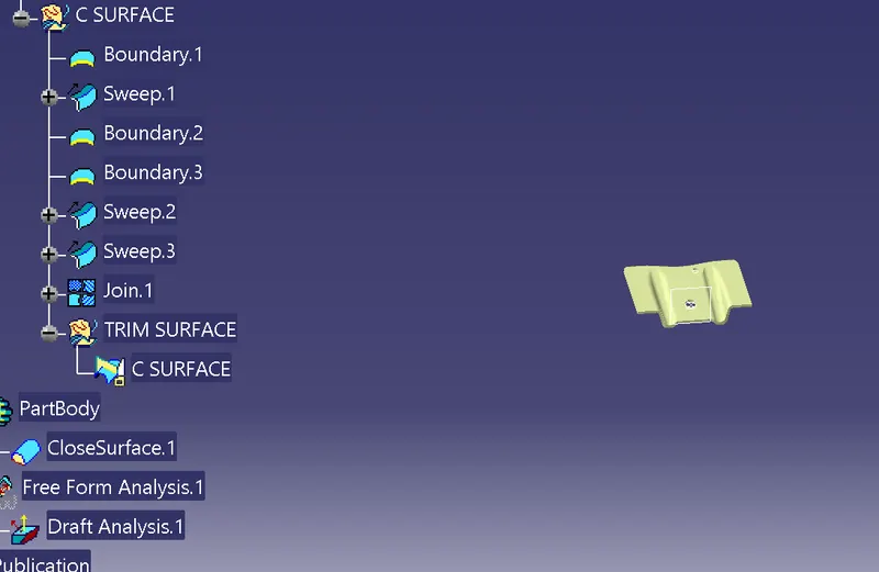
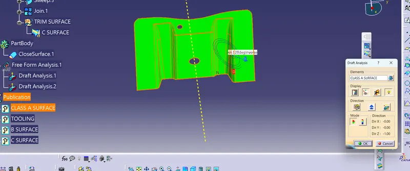
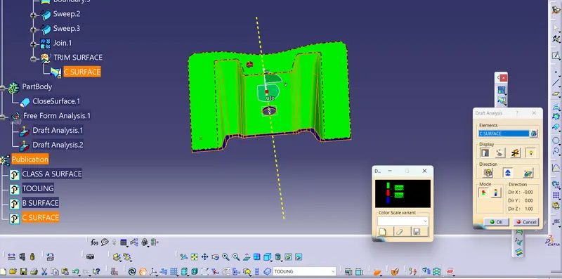
DRAFT ANALYSIS
CLASS A SURFACE
C SURFACE
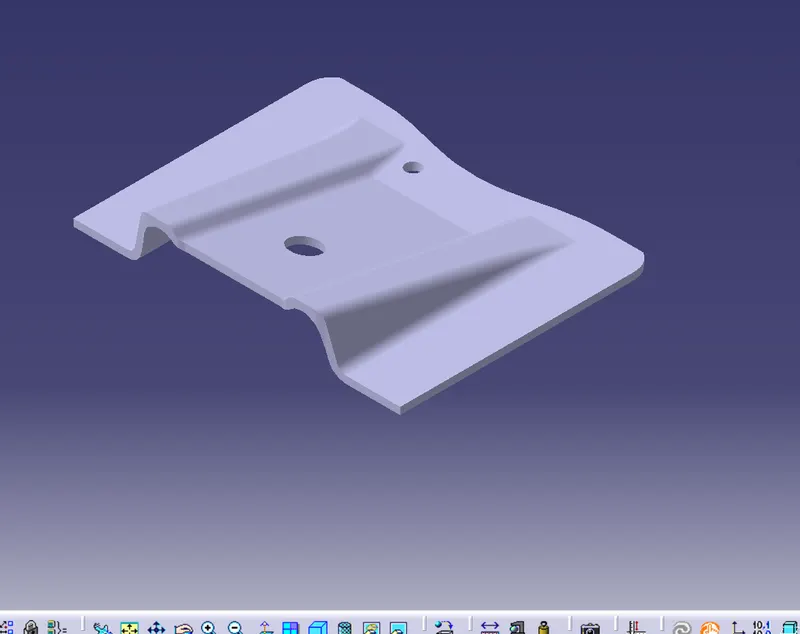
ISOMETRIC VIEW
FRONT VIEW
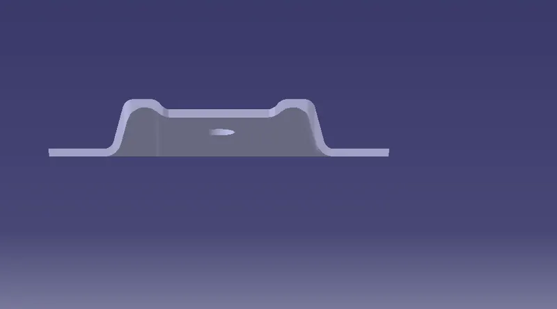
SIDE VIEW
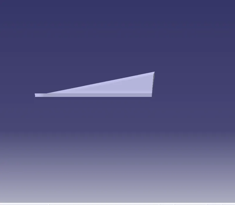
TOP VIEW
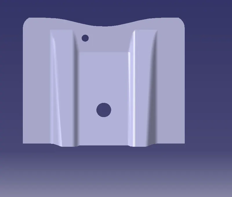
DETAILED REPORT
- To open the given class A surface
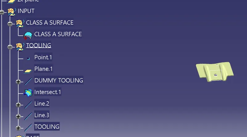
- Create geometry set TOOLING and Create a POINT and DATUM PLANE with respect to YZ PLANE
- To create a dummy Tooling axis with respect to INTERSECTION
- To create a LINE 1 & LINE 2 with respect to the intersection and
- To create BISECTING LINE as TOOLING AXIS.
- To create a Geometry set name as B SURFACE
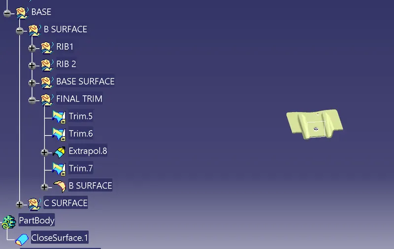
- B SURFACE has RIB 1 & RIB 2 to be created with the EXTRACT -> UNION TRIM -> EXTRAPOLATE -> TRIM -> OFFSET
- To create a BASE SURFACE and Create FINAL TRIM
- FINAL TRIM to be created and used EDGE FILLET with radius 3mm.
- EDGE FILLET Name as B SURFACE
- To Create C surface
- Boundary to be created in A SURFACE
- By using SWEEP command and JOIN the surface and TRIM the SURFACE
- After creating C SURFACE open the Draft analysis with the Tooling direction.
- OPEN the PART WORK BENCH create the close surface and select the C SURFACE.
DRAFT
STEPS
- Set the customized render style
- Select the Draft analysis Tool
- Adjust the draft direction to moulding axis using the compass
- Observe the colour ranges
GREEN - 3 degree above
RED - 0 degree below
BLUE - 0 ~ 3 degree
RESULT
Thus, Base Bracket Plastic component through the given Class-A surface. To begin with, the tooling axis for the given Class-A Surface should be created meeting the requirements of the draft angle and at the end perform the Draft analysis on the model to be completed.