Week 9 - Challenge 1 - Base Bracket Design
Report
Aim -
- To create the Base Bracket from the given Class-A surface.
- Determine the Tooilng Axis and design the Class-B & Class-C surfaces, while meeting the requirement of the Draft Angle.
- Perform the Draft Analysis of the class-A surface and the final solid surface.
Thickness of the plastic part is to 2.5mm.
Designed of the part -
- The given surface is a Class-A surface. It describes the surface data of a part, which shows it’s aesthetics. The final production model has the surface finish of the Class-A surface. These surfaces has the highest quality surface finish and should be error free as well.
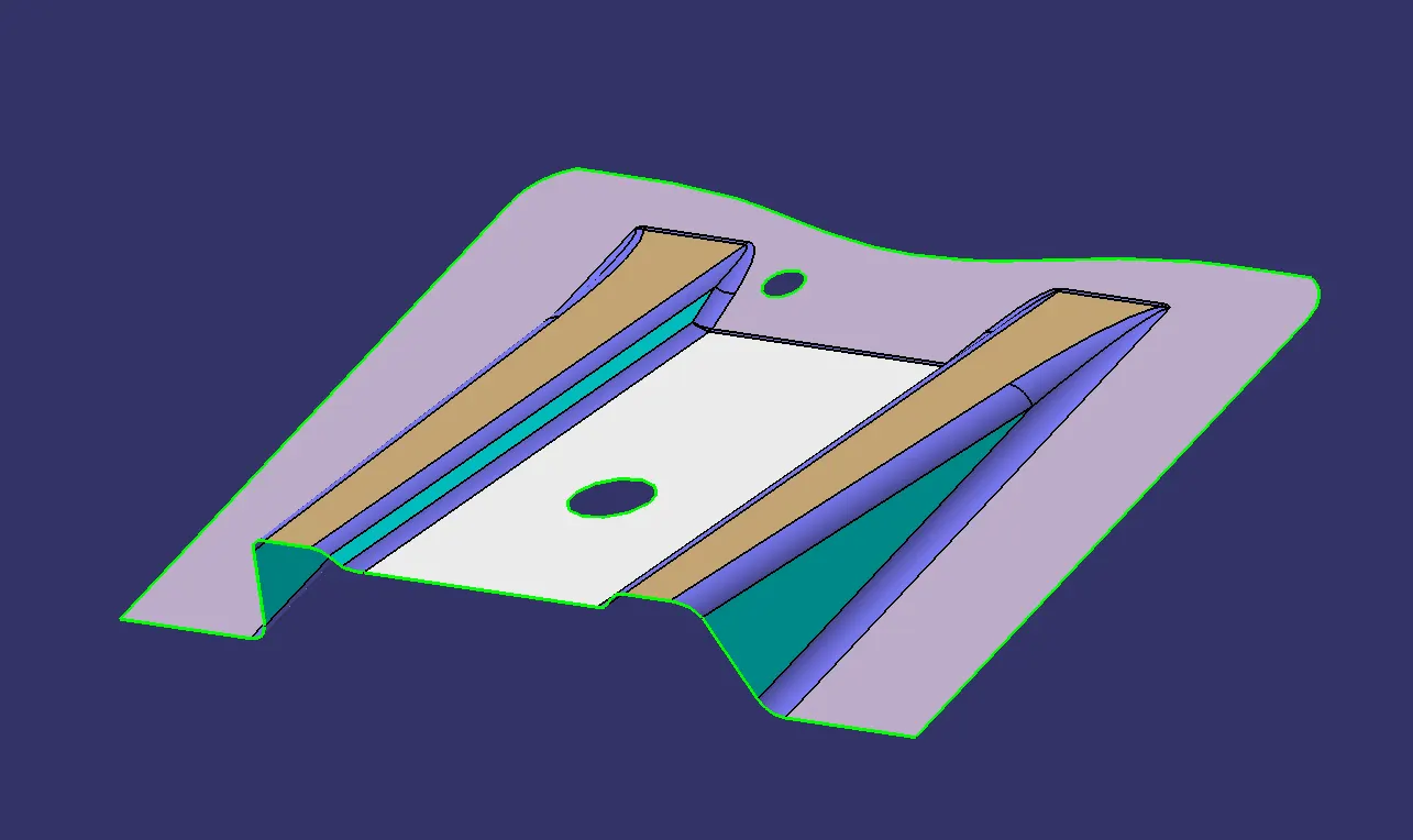
- We have to design the Class-B and Class-C surface from the Class-A surface.
- Class-B surfaces are the second surface of the part which normally isn't visible from the outside. These surfaces also need to have high surface finishes and low errors, but not as much as Class-A surfaces.
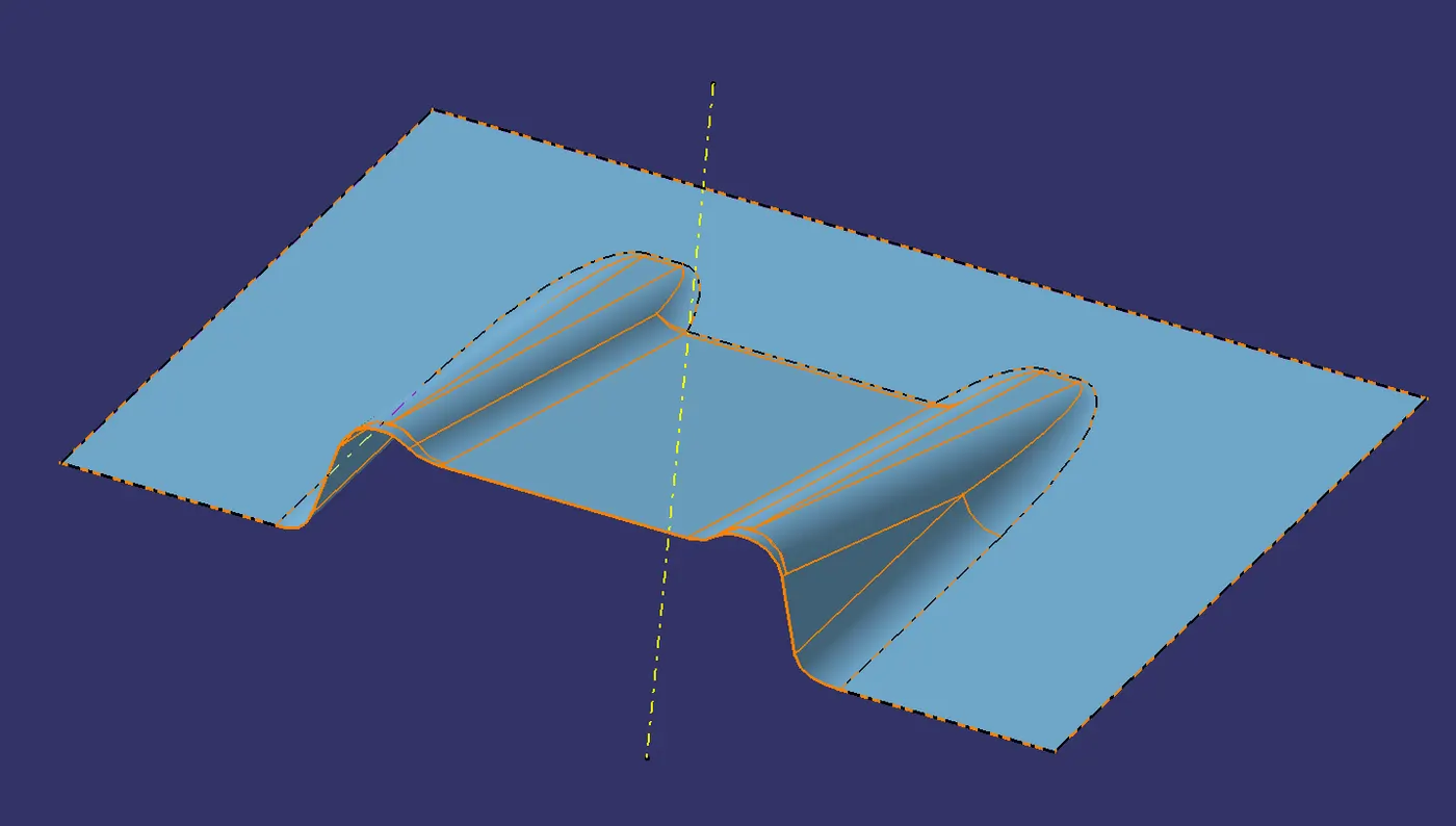
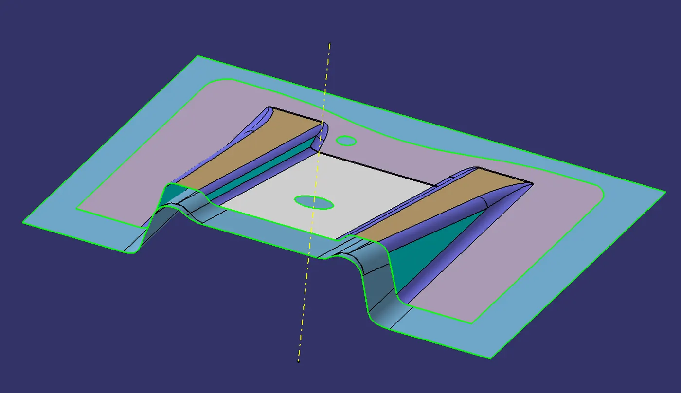
- Class-C surfaces are allowed to have some tool marks and other imperfections which reduces the surface finish of the part. It’s a surface which joins the Class-A surface with the Class-B surface.
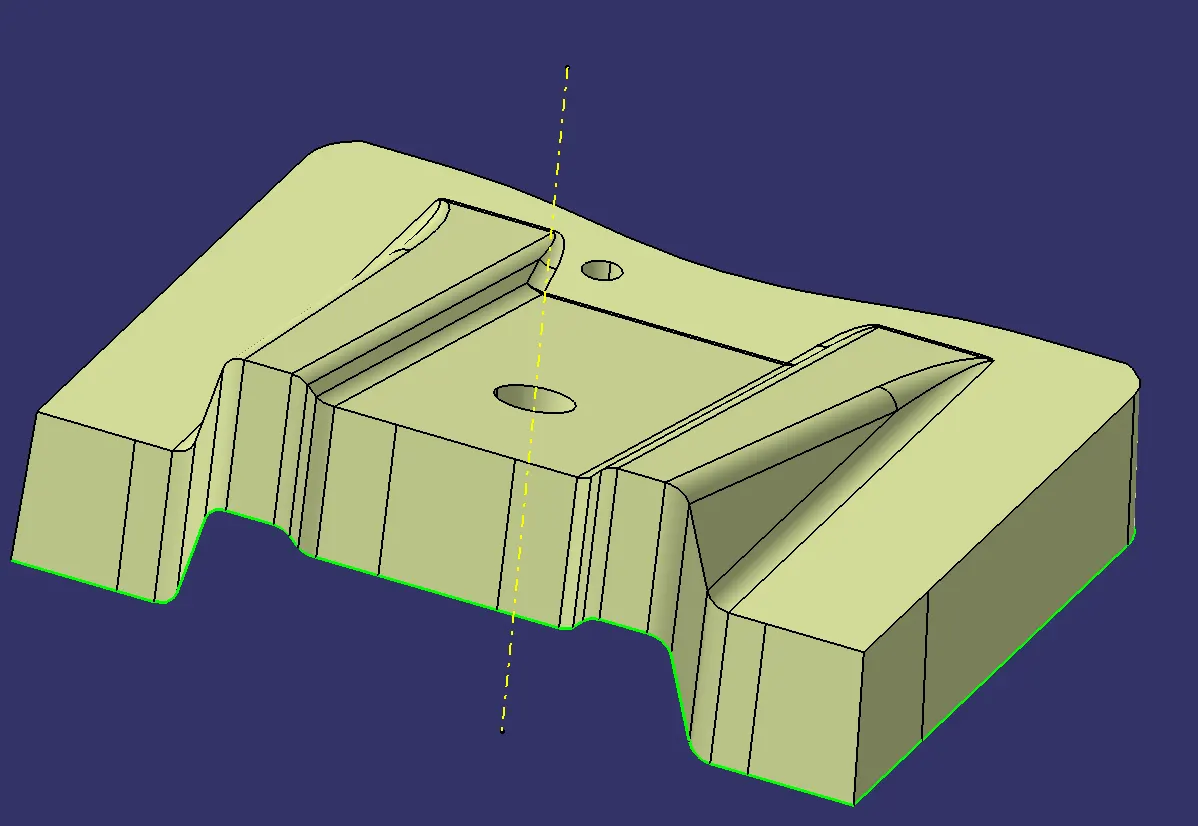
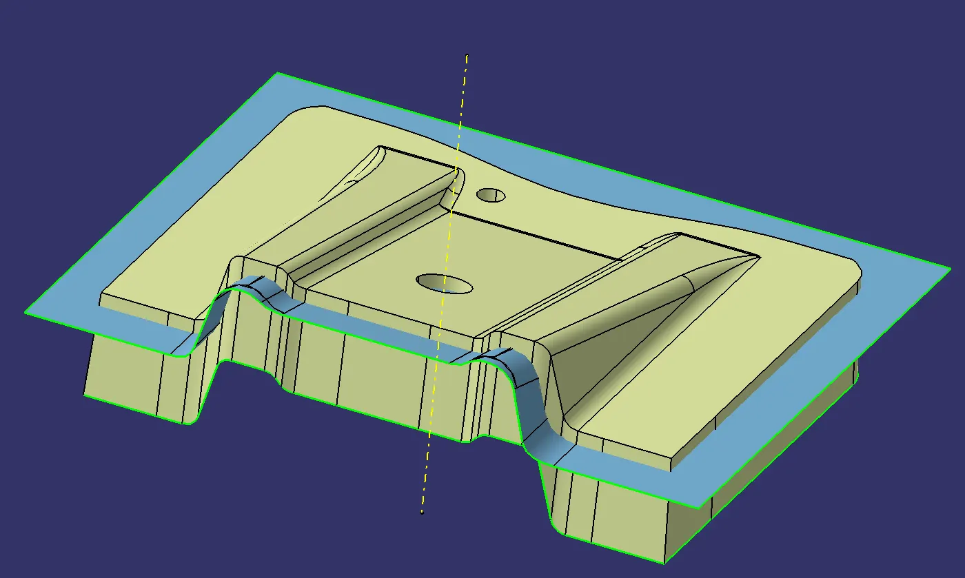
- The final hollow surface is designed by trimming and joining the Class-A, Class-B & Class-C surfaces.
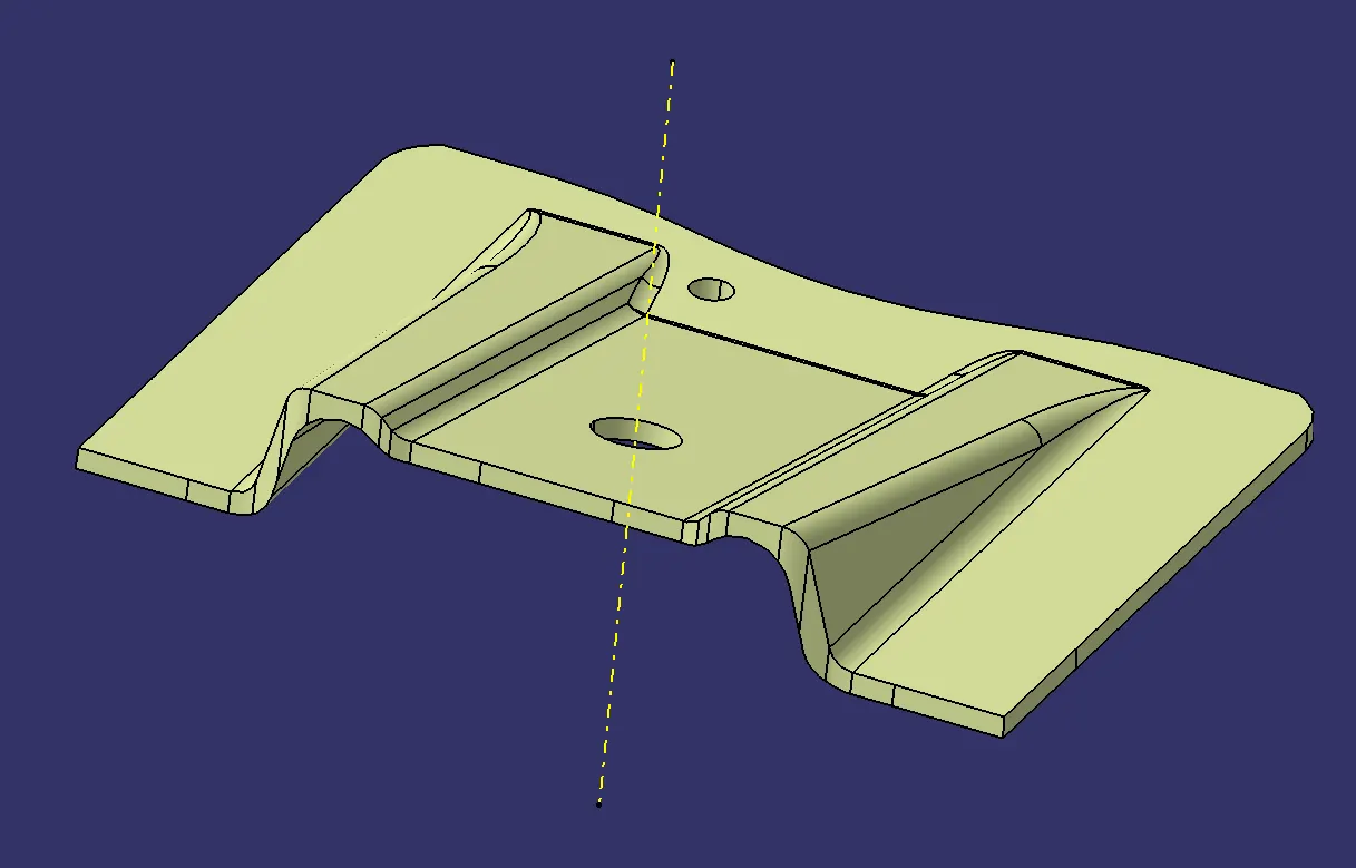
- The surfce part is converted to solid part in part design by using the solid body command.
The finished product -
Isometric View
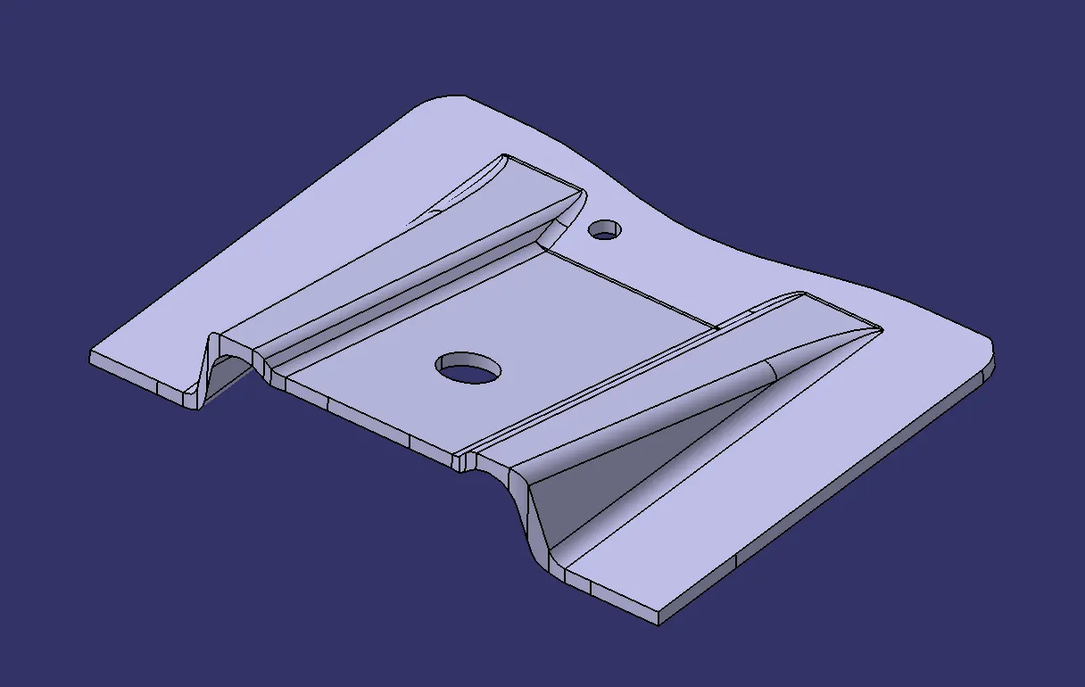
Front View
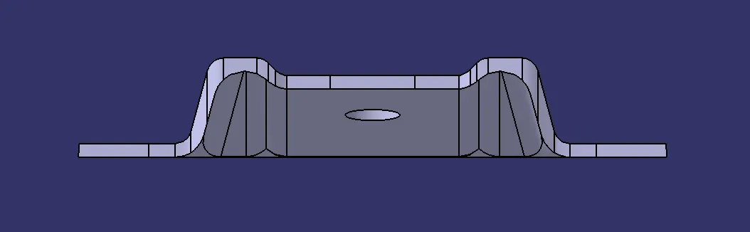
Side View
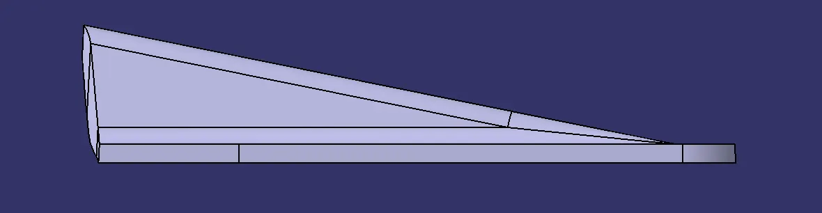
Top View
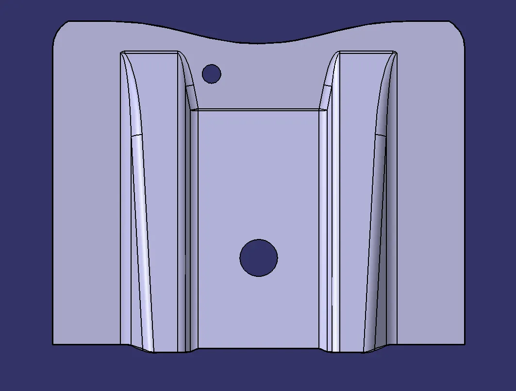
Creating a Tooling Axis (Direction) -
A mould is built into two separate pieces, a Cavity side and the Core side. The Tooling Direction is the direction that the mould pulls away from each other. The direction by which the Core pulls apart from the Cavity is called the Tooling Direction. The angle at which the mould and part has towards the tooling axis is the draft angle.
The methods used here to find out the tooling direction is the bisecting method. A better tooling direction can reduce the cost of manufacturing by reducing the complicity in manufacturing the component.
The Bisecting Method consists of the following steps -
- Check surface continuity of the Class A surface and repair any discontinuity like breaks and disjoints.
- Create a tooling axis for reference and analyse the components and their angle to the reference axis.
- Take an intersection to the part with a perpendicular plane and get a profile of the section.
- Create lines on the angled sections of the part body which could interfere with the draft angle and tooling direction on both sides of the part.
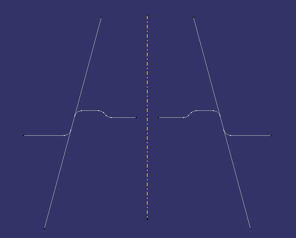
- Create a bisecting line to the two or more lines produced from the angled surfaces. This is the tooling direction for the current plane being worked on.
- Repeat the process for the other intersection produced by the other perpendicular plane.
- Take a bisecting common axis if the two planes produce two different axes. This common axis is the tooling axis which determines the tooling direction and draft angle.
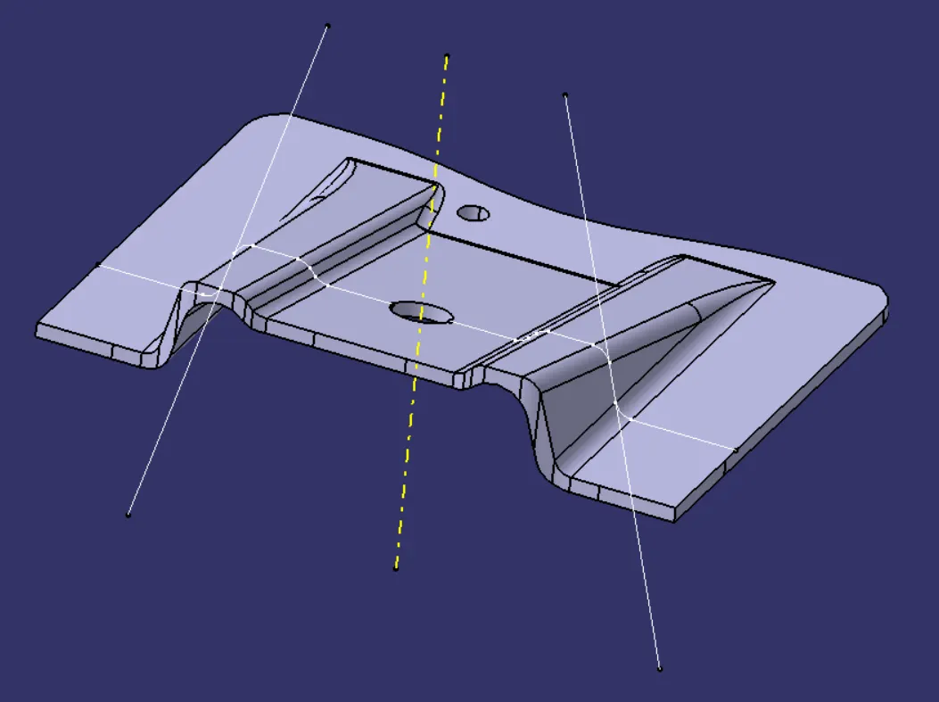
Performing a Draft Analysis -
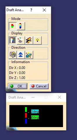
Draft Analysis command window and colour scale variations.
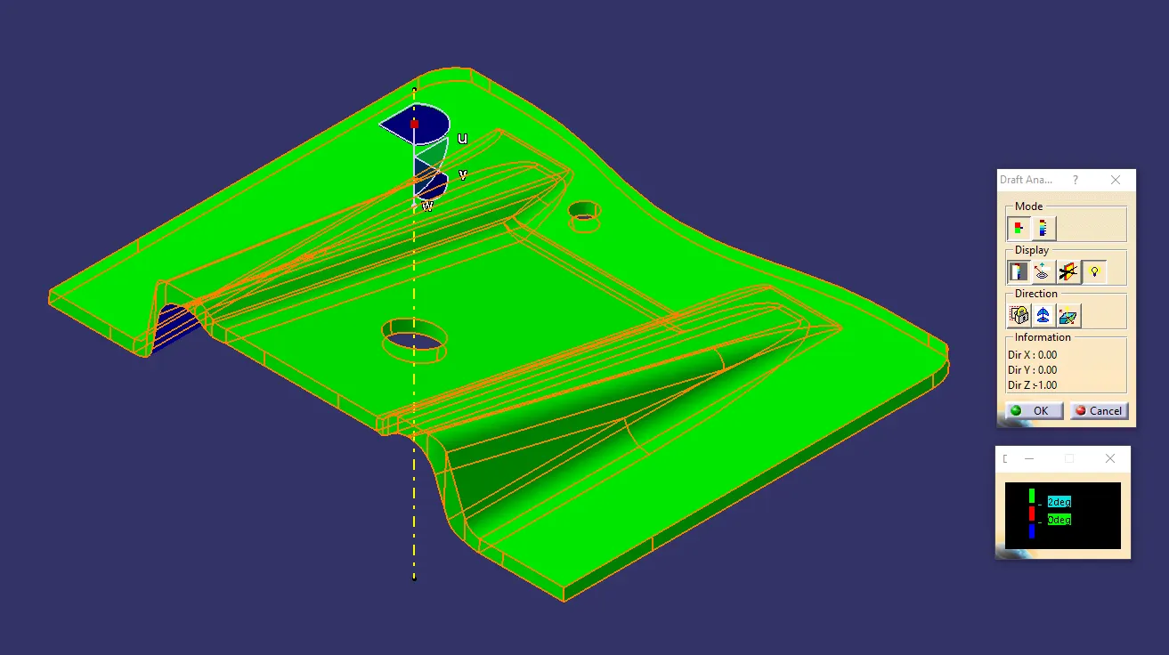
- Draft Analysis on the Class A surface.
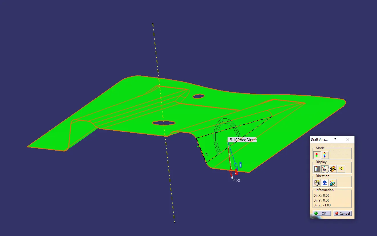
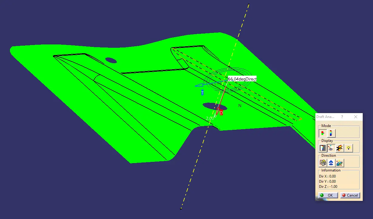
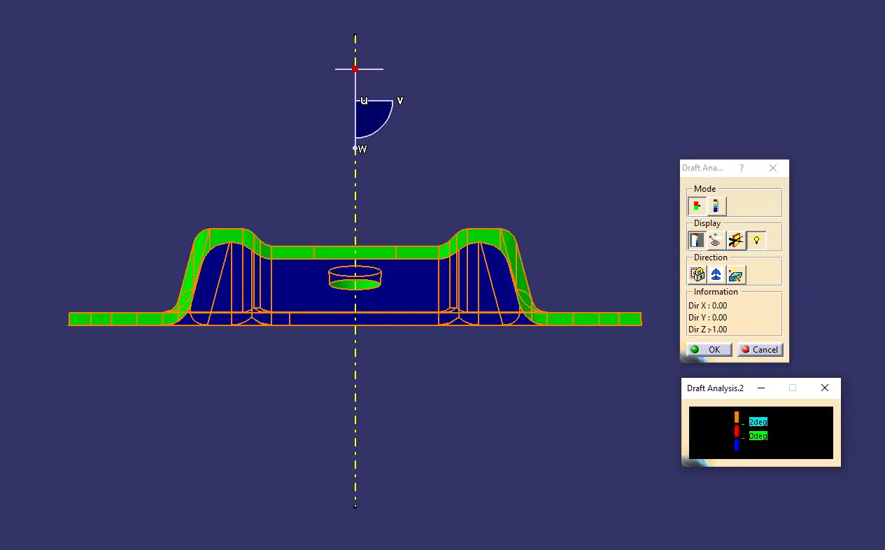
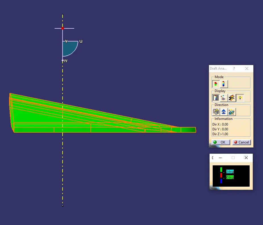
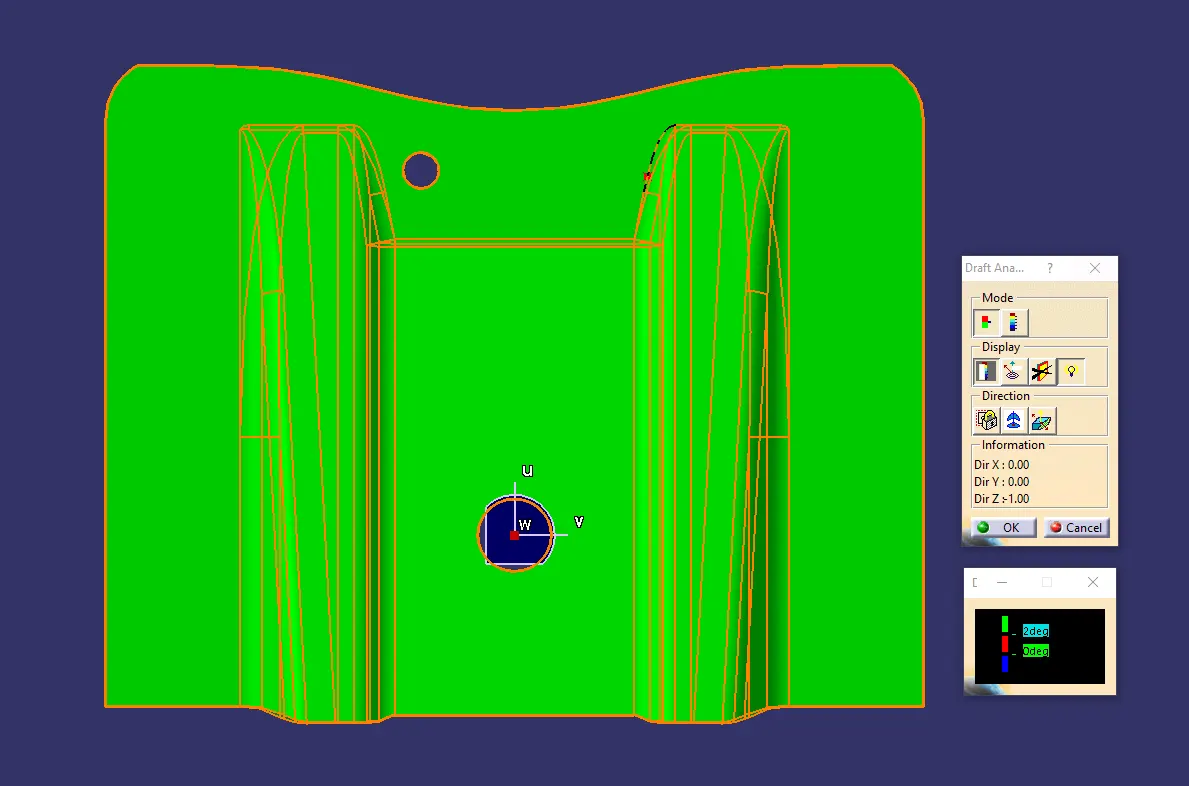
- Draft Analysis on the final solid part.
Isometric View -
Front View -
Side View -
Top View -
Conclusion -
- Tooling Direction is determined and draft angle is set to 3deg.
- The Part’s Class-B, Class-C and solid surfaces are designed in accordance to the draft angle and tooling direction.
- Draft analysis is conducted on the provided Class-A surface and the finished solid part, with the result being the part has positive draft and is manufacturable.