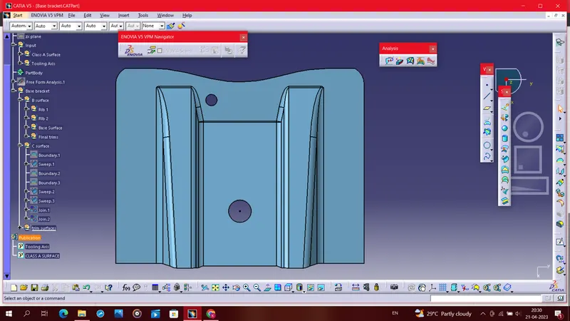
Challenge

Week 9 - Challenge 1 - Base Bracket Design
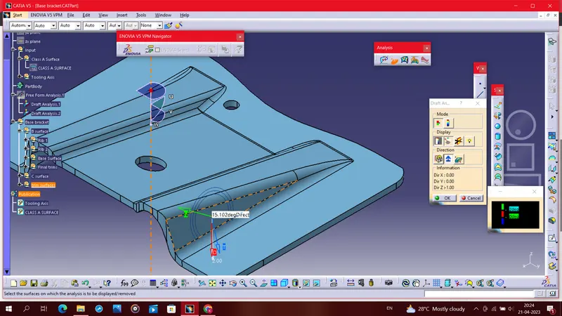
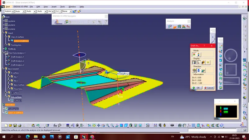
Draft Analysis

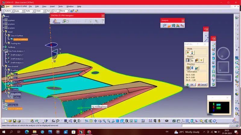
Draft analysis is a very important tool used for verifying the manufacturability of a part or product. Here are the steps to perform a draft analysis.

  1. Go to the "Analysis" toolbar and select "Draft Analysis."

  2. A "Draft Analysis" dialog box will appear. In this dialog box, select the surfaces or faces that you want to analyze for draft angles.

  3. Select the "Direction" option and choose the direction in which you want to analyze the draft angles. It can be choosen between the X, Y, or Z axis.

  4. In the "Draft Angle" section, set the minimum and maximum values for the draft angles that needs to be analyzed and can also choose to display the analysis results in degrees or in percent.

  5. Click on "Apply" to perform the draft analysis on the selected surfaces or faces.

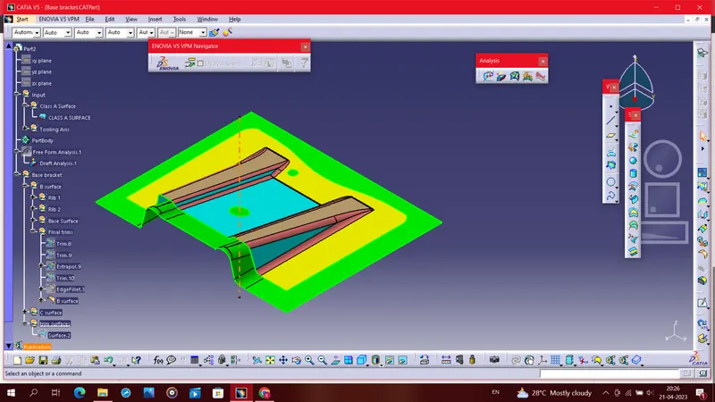
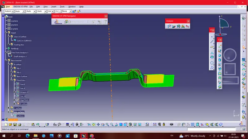
  6. The results of the analysis will be displayed in a color-coded format, where the areas that meet the draft angle criteria will be displayed in green, and the areas that do not meet the criteria will be displayed in red.

  7. If necessary, can adjust the draft angles and re-run the analysis to check the manufacturability of the part or product.
Tooling axis creation
Tooling axis refers to an imaginary axis that is used as a reference line for designing molds, dies, and other tooling components. The tooling axis is defined by the designer based on the part geometry and the requirements of the manufacturing process.
The tooling axis is critical in the design of molds and dies because it determines the direction in which the mold or die will open and close, and it helps to ensure that the part will be ejected from the mold or die properly. The tooling axis is also used to define the orientation of the part during the manufacturing process, such as during machining or injection molding.
In CATIA V5, the tooling axis can be created using the "Tooling Axis" option in the "Axis Systems" toolbar. This allows the designer to define the start and end points of the tooling axis and to specify its orientation with respect to the part geometry. By creating an accurate and efficient tooling axis, designers can ensure that their molds, dies, and other tooling components will perform optimally during the manufacturing process.
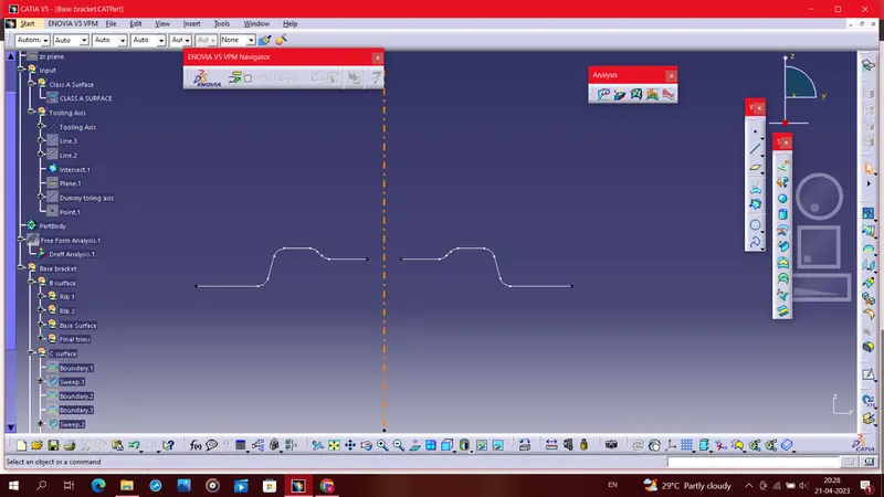
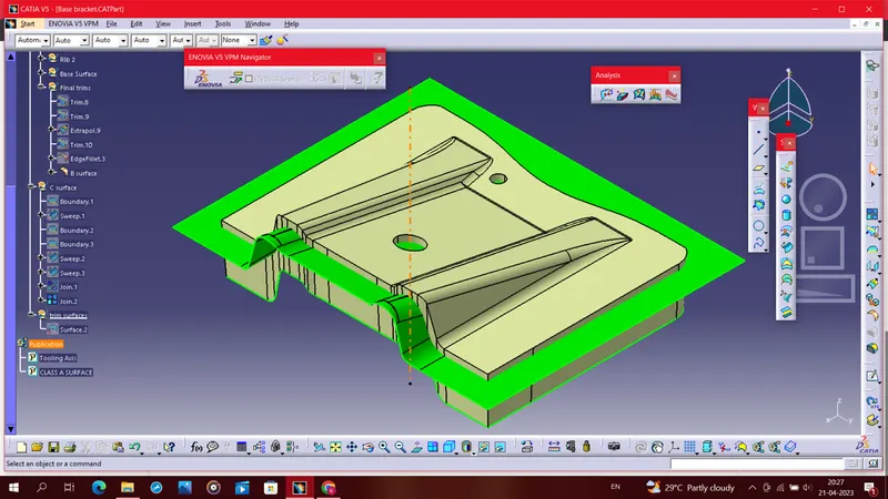
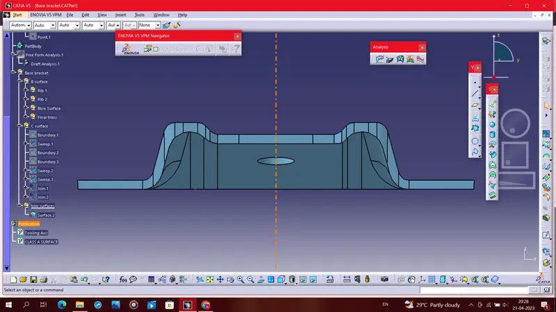
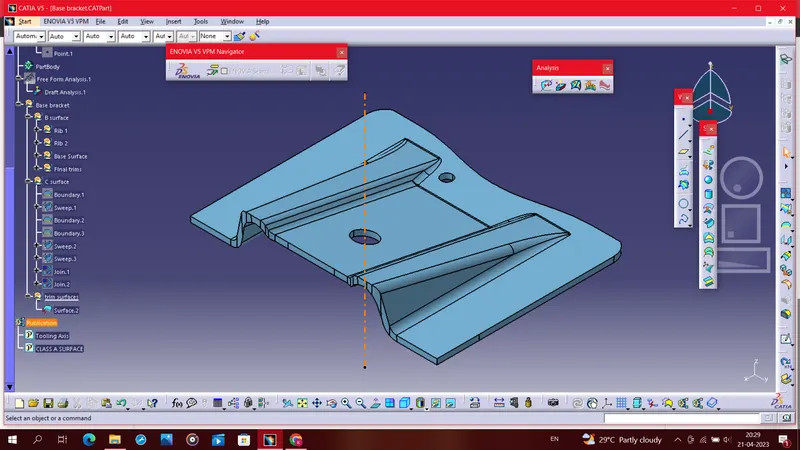
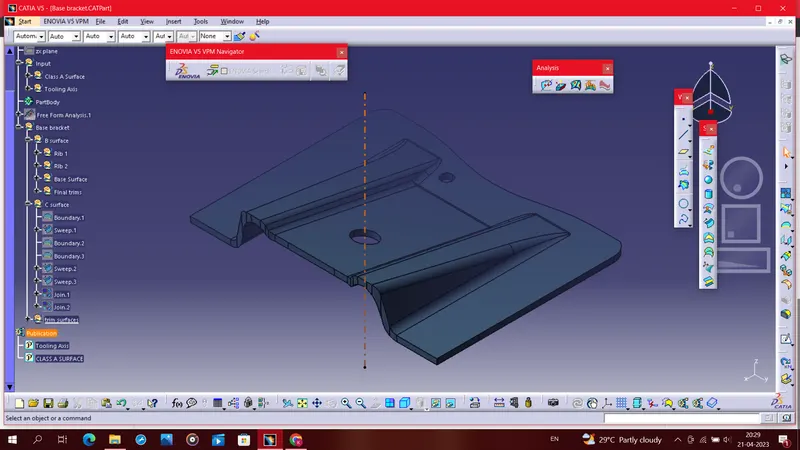
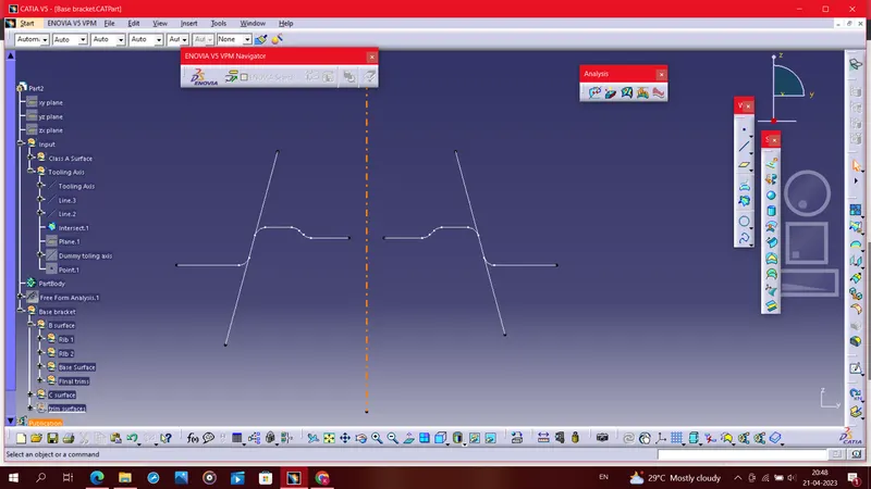
firstly dummy tooling axis is created by analysing the A class surface, where it is intersected along the any x, y, or z direction so that the material can be obtained in that particular direction.
then the with the extracted boundary using the inclined planes bisecting line is created using the centre point which becomes the tooling axis.
please find the below snap for explanation
in the above snap using intersection tool to intersect the surface, using line 2 & line 3 along the inclined lines.
By using the bisecting line comand the tooling axis is created.
Your portfolio, next

Ship work like this
in your own course.

Talk to a career counsellor

Free 20-minute call. We'll map the right course to where you want to work.

By submitting you agree to our Terms and Privacy Policy.