Week 9 - Challenge 1 - Base Bracket Design
REPORT
OBJECTIVE:
The objective of the project is to design the class B and C surface for the Base bracket with the given class A surface and Draft analysis must be carried out by creating a perfect Tooling direction by using the Bisecting method.
INTRODUCTION:
The Draft Analysis command enables you to detect if the part you drafted will be easily removed. This type of analysis is performed based on colour ranges identifying zones on the analyzed element where the deviation from the draft direction at any point, corresponds to specified values.
Tooling direction is the main consideration for plastic part and mould parts because it defines the movement of the mould part and the possibility of the plastic part coming out from the mould part (Core and Cavity).
Tooling Direction:
- In Molding, machine arrangement is given to open the mould along a direction which is known as Tooling Direction.
- The mould is built from two separate halves (Core and Cavity) and tooling direction basically defines the direction of mould pulls apart.
- Tooling direction is known as primary direction.
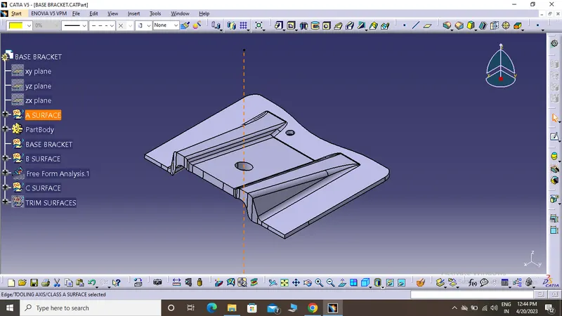
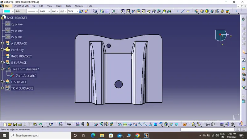
CLASS A SURFACE PROVIDED BY THE STYLING TEAM
PROCEDURE FOR CREATING THE TOOLING DIRECTION
- First, the given styling surface (class-A) imported into the generative shape workbench in CATIA and checked for irregularities by using Join or Boundary command. If there are no irregularities then it’s good to go or else the irregularities must be fixed first.
- Then the hole which is visible from the z-direction was taken into account and a point was created and by using it a line was created along the z-direction and named it a dummy tooling axis.
- Then by using the point axis system was inserted and by using the xz plane intersections were created on the class A surface.
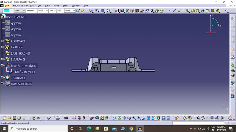
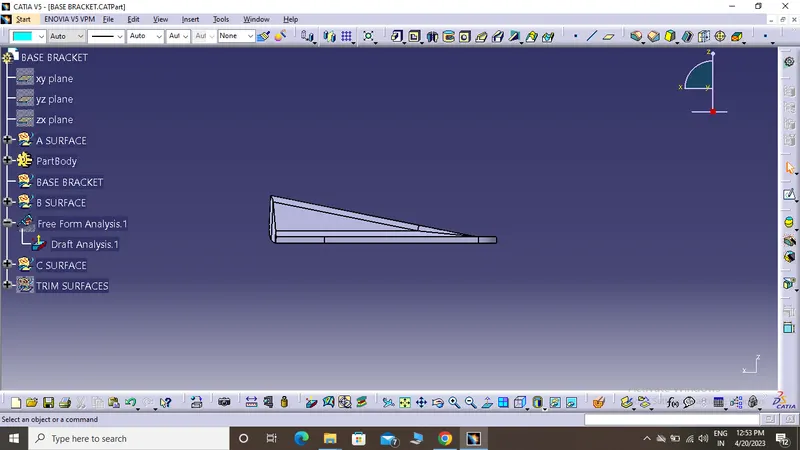
- Then by using point to point line as shown in the below figure sidelines were created and by using the bisecting method the Tooling Direction was created and subjected to draft analysis.
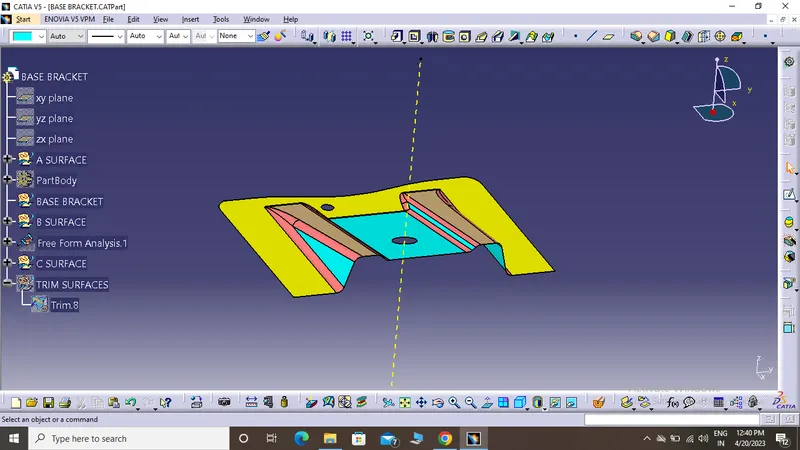
- By using the feature draft analysis tool the class A surface was analyzed for the created tooling axis with the compass locked to it. (Note: The Nominal draft angle is 3 degree for Plastic parts)
- CREATING CLASS B SURFACE
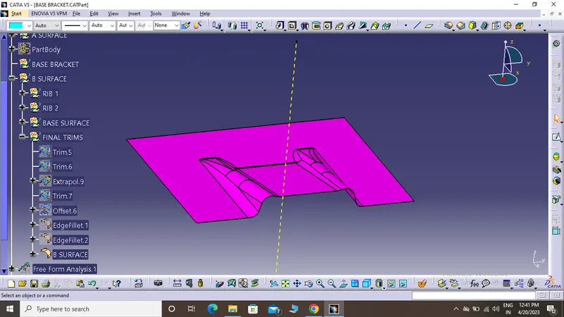
Class B surface is generally called the engineering surface where all the ribs and fixation points present.
Class B surface for the base Bracket was designed to step by step by creating the ribs first and then the base surface.
- First by using the extract option (no propagation) the required faces of the rib from the class A surface was extracted and then the extracted surface were untrimmed.
- Then the untrimmed surface was extended by using extrapolate command for getting better interference between the surface.
- Then the required portions were trimmed from the extrapolated surface.
- Then both the ribs were offset to 2.5mm as per the guidance.
- For the base surface, the required surface was extracted separately and un-trim operation was carried out following the extrapolation.
Then the surfaces were again offset to 2.5mm and finally, the required portions were joined by using the trim option and finally the required fillets were applied. (3mm)
- Class C surface is the surface that joins the Class A & B surfaces together.
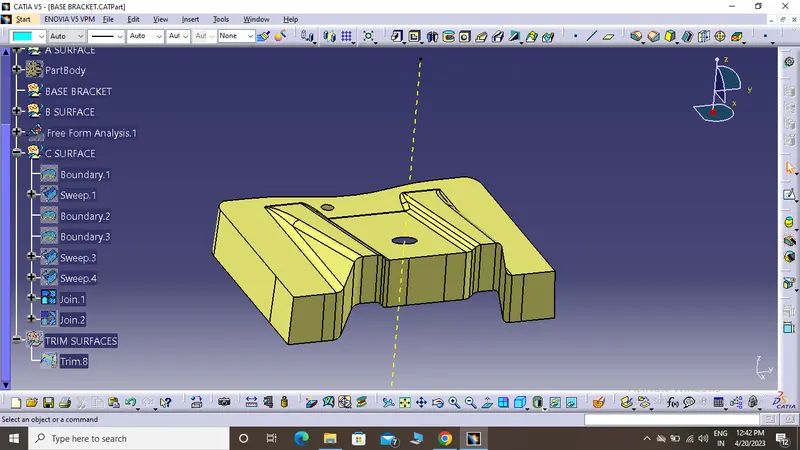
- The class A surface outer boundary is extracted and by using the swept surface tool, along with the draft direction option the guide curve is selected as the extracted outer boundary and for the draft direction the created tooling directions were selected and the downward direction were selected and finally the class C surface was extruded.
- Then by following the same method the two holes were generated and joined together to form a complete surface with no gaps.
- Then the required surface was trimmed and renamed as a Base Bracket.
- Then the required Tooling Direction and Class A, B & C surfaces were published by using the Publication command from the tools option.
- CONCLUSION
- From the given class A surface the Class B and C surfaces for the Base Bracket were created and by creating a tooling direction for manufacturing the Base Bracket was analyzed and found successful.
IMAGES:
CLASS A SURFACE:
CLASS B SURFACE:
CLASS C SURFACE: