Attachment Feature Creation (Ribs & Screw Boss) - Challenge 1
1. Aim
To Create an Solid Component along with some Engineering Features such as Ribs and Screw Boss from the given Class A surface. Also the Engineering or B side Features should be designed as per the Design Standards.
2. Engineering Features
2.1 Ribs
For an Plastic component, the ideal Thickness would be 3mm with a deaviation of +-30%. Here, Ribs are used to increase the Stiffness and Strength of an moulded part without increasing any overall thickness. It is also used for
- Locating and Arresting components of an assembly.
- Providing alignment in mating parts.
- Acting as stops or guides for mechanisms.
There are certain rules to be followed when designing an Rib and they are
- Rib Wall Thickness should be o.4 times more than the main thicknes. At the tip of the rib, it should have minimum 0.75mm.
- Rib Height should be 5 times more than the main thickness.
- Optional Fillet Radius is 0.25mm.
- Draft degree should be 0.5 along the draft direction or the Tooling Axis.
- Root Thickness of the Rib should deviate more than 30% of the main thickness.
- Spacing between two ribs should be more than, 2 times more than the main thickness.
2.2 Screw Boss
It is an feature which helps to Screw two components together. Screw boss also has certain design rules and they are
- The wall thickness of the Screw Bosse should be 0.6 times the main thickness
- Fillet Radius should be 0.25mm.
- Draft degree should be 0.5 for both inner and outer surface and it should also drafted along the Tooling Axis
- Height of the Screw Boss should be 3 times more than the diameter of the hole.
3. Procedure
3.1 Work Flow Pattern
- Creation of Tooling Axis
- Creation of B Surface
- Creation of C Surface
- Creation of Ribs and Screw Boss
- Assembling
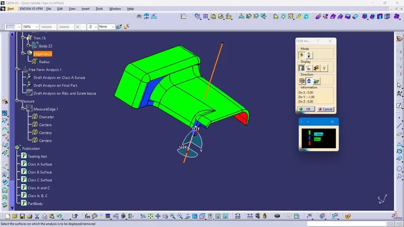
- Draft Analysis
3.2 Creation of Tooling Axis
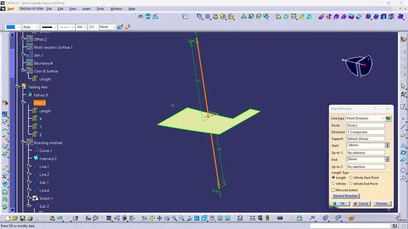
For the Creation of Tooling axis, Normal to surface method was used and bisecting method is not used because there's only fillets which are parallel and they are not bisecting each other. So, Normal to Surface method was used.
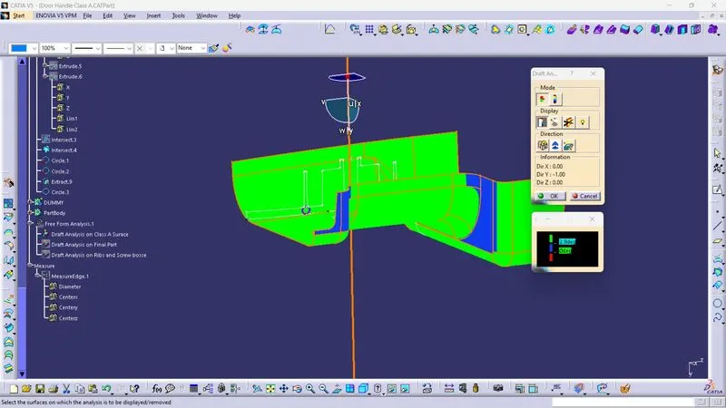
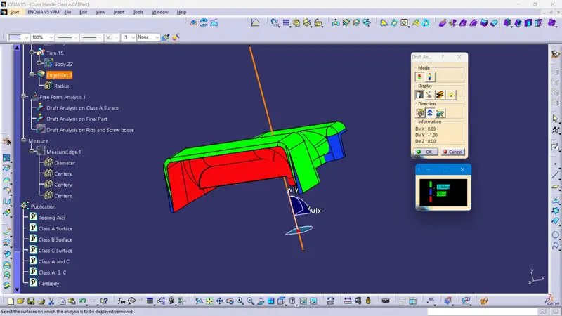
While Performing the draft analysis there are some blue patches which has less than 3 degree of draft. Other methods were also used but those pathches can't be drafted at 3 degree. This Class A Surface has an defect and it can't be fully drafted at 3 degree.
3.3 Creation of Class B Surface
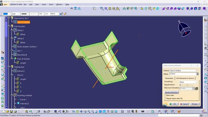
The thickness of the component is not provided, so it was assumed to be 2.5mm. With this the class A surface was offseted to 2.5 mm to create class B surface. A small portion of the fillet region got convexity error and it formed a hole. This hole was filled by using Multi Section Tool and finally the edges were extrapolated for 3mm.
3.4 Creation of Class C Surface
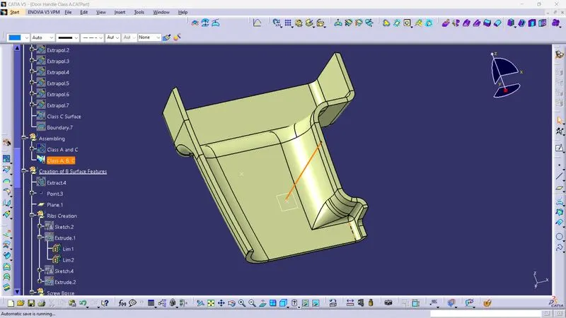
Class C Surface is nothing but the surface which joins Class A and B. For the Creation of Class C Surface
- The surface which are perpendicular to the tooling axis will be Sweeped along reference to surface method at 90 degree angle.
- The surface which are parallel to the tooling axis will be Sweeped along draft direction method at 3 degree angle.
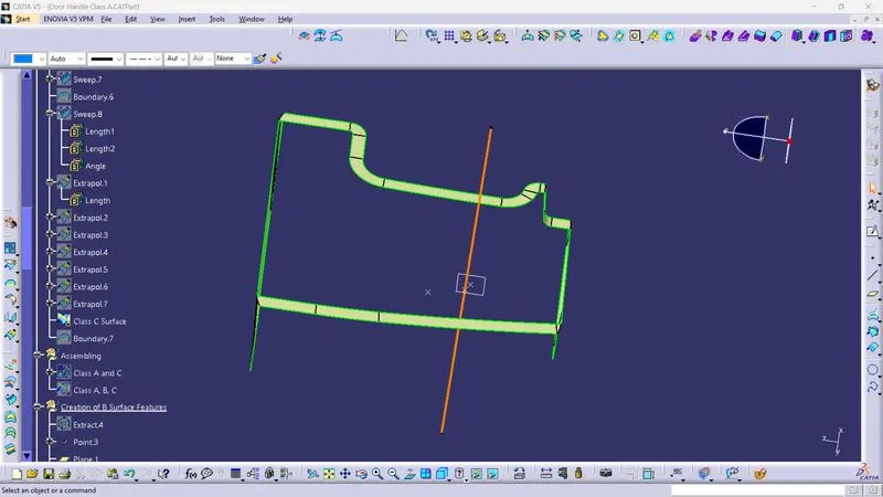
After the Creation of Class C, Class A and C surface was joined and trimmed along the Class B Surface to create the final Closed surface.
Then in part workbench it was converted into Part by using Close Surface Tool.
3.5 Creation of Ribs and Screw Boss
3.5.1 Ribs
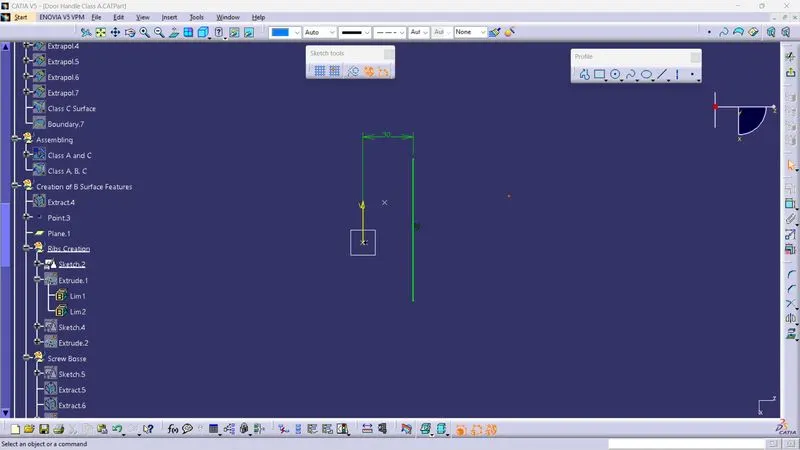
For the creation of Ribs, a flat B side surface was extracetd and created a plane tangent to it. With the created plane, Skectches were drawn --> extruded --> Thickened --> Assembled to the main Part using Union Trim Command.
- Rib wall thickness - 0.4*2.5 = 1mm
- Rib Height - 5*2.5 = 12.5mm
- Fillet Radius - 0.25mm
- Draft - 0.5 degree
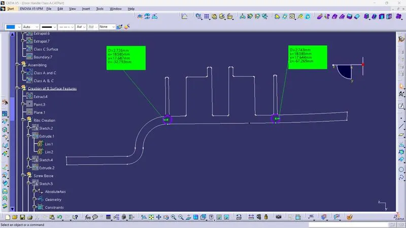
- Rib Root Thickness - ~2.73mm
Rib Sketch:
Rib Root Thickness:
3.5.2 Screw Boss
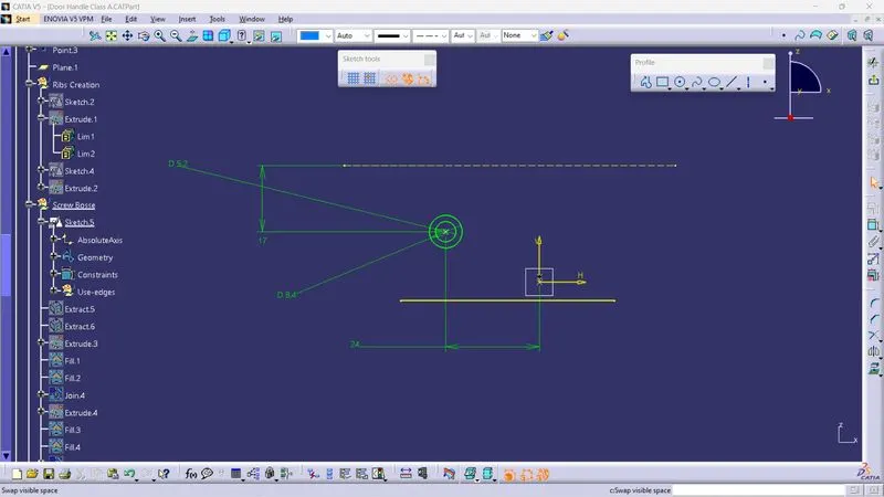
For the creation of Screw Boss, the plane which was created for Ribs, was used. Skectches were drawn --> extruded --> Thickened --> Assembled to the main Part using Union Trim Command. Additional Ribs for Screw Boss were created with the same designe rules and dimensions which followed in 3.5.1 .
- Screw Boss Inner Diameter - 5.2mm
- Screw Boss Thickness - 0.6*2.5 = 1.5mm
- Screw Boss Outer Diameter - (1.5*2)+5.2 = 8.2mm
- Fillet Radius - 0.25mm
- Draft - 0.5 degree
- Screw Boss Height - 3*5.2 = 15.6mm
Screw Boss Sketch:
3.6 Assembling
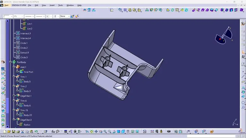
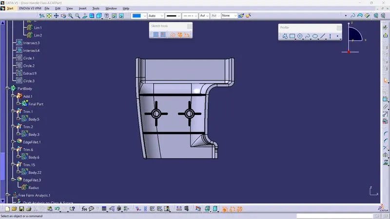
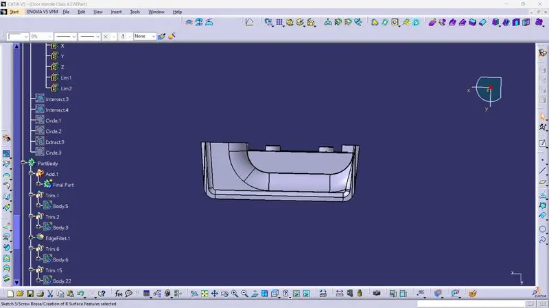
After the Thickening method all the parts were assemble into the Main Part by using Boolean Operations
Isometric View:
Top View:
Front View:
3.7 Draft Analysis
3.7.1 Draft Analysis on Final Part
On the Final part, draft analysis was performed at 2.9 degree.
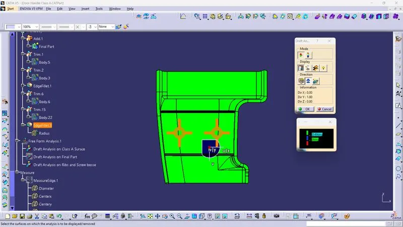
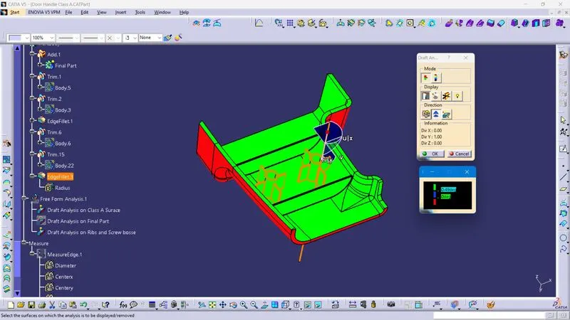
3.7.2 Draft Analysis on Engineering Features
On Ribs and Screw Boss, draft analysis was performed at 0.49 degree.
4. Conclusion
With the given Class A surface as an input, Tooling Axis, Class B Surface , Class C Surface, Ribs and Screw Boss were Created. Also Draft Analysis was performed at 2.9 degree on Final component and 0.49 degree on Ribs and Screw Boss.