Week 9 - Attachment Feature Creation (Ribs & Screw Boss) - Challenge 1
ATTATCHMENT FEATURE CREATION (RIBS AND SCREW BOSS)
Objective
The main objective of this challenge is to create the B-side features RIBs and Screw Bosses for a given drill handle.
Overview
Creating the class B and class C surfaces to the door handle, and creating the B side features (RIBs and Screw Bosses) by considering all the
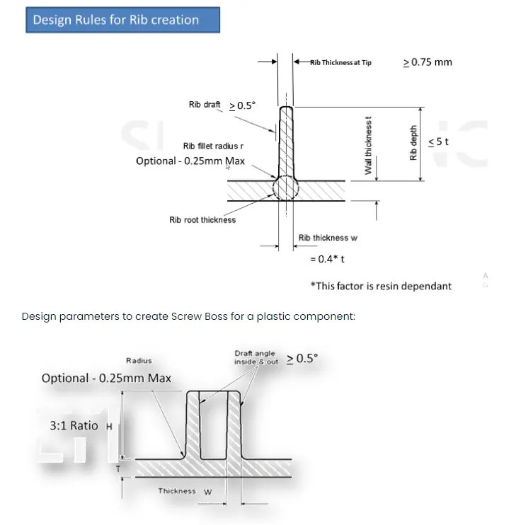
design parameters. Design parameters to create RIB for a plastic component
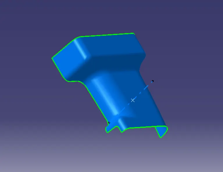
CLASS A TOOLING AXIS AND DRAFT ANALYSIS
To create the tooling axis, I extracted the surface of class A with no propagation and I created the point at the centre of the extracted surface and
created a line at that point in the Y direction. After creating the Tooling axis, I performed a draft analysis for class A to check the draft angle for it.

Class B surface
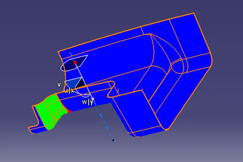
To create the class B surface for the door handle, I offset the class A surface to 2.5mm inside. Once the class A surface is offset created, according
to the thickness, we can observe some patches on the offset surface due to the fillets on the class A surface. Now, we need to close those patches.
I used multi-section solid command to close the patches.
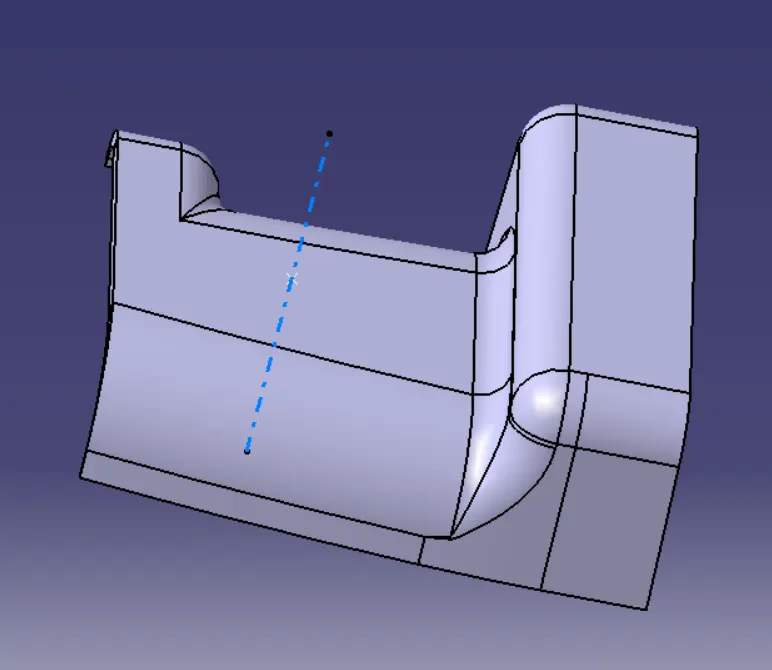
Class C Surface creation
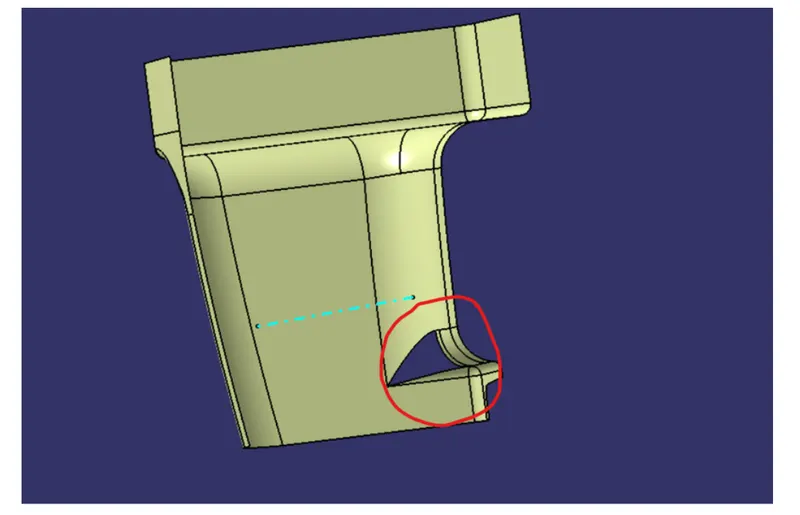
I used the sweep command in the geometric shape design workbench to create the class C surface.Initially, I extracted the edges of the class A
surface with tangent continuity by using the multiple extract command. After extracting the class A surface edges correctly, I sweeped the
extracted edges with 93deg toward the class B surface. After sweeping the extracted class A surface edges, I extrapolated the edges of the sweep
for 2mm to intersect the sweep edges with each other. Now I trimmed the extrapolated surfaces together to create a complete sweep surface
towards the class B surface. I joined both the trimmed sweep surface and class A surface together, to get the class A+C surfaces as a single
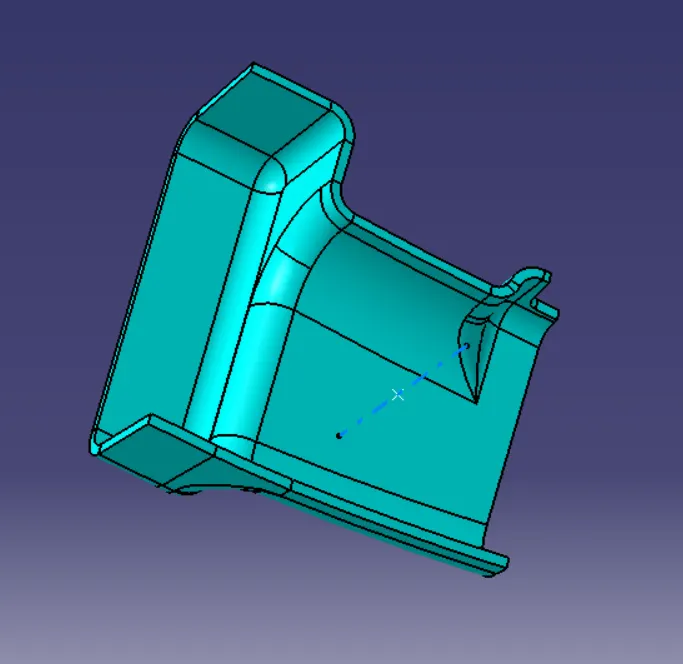
surface. Now, to create a solid body for the door handle we need a closed surface. I trim the class B surface with joined class A+C surface to make
the closed surface of a door handle.
CLOSED BODY
RIB DESIGN
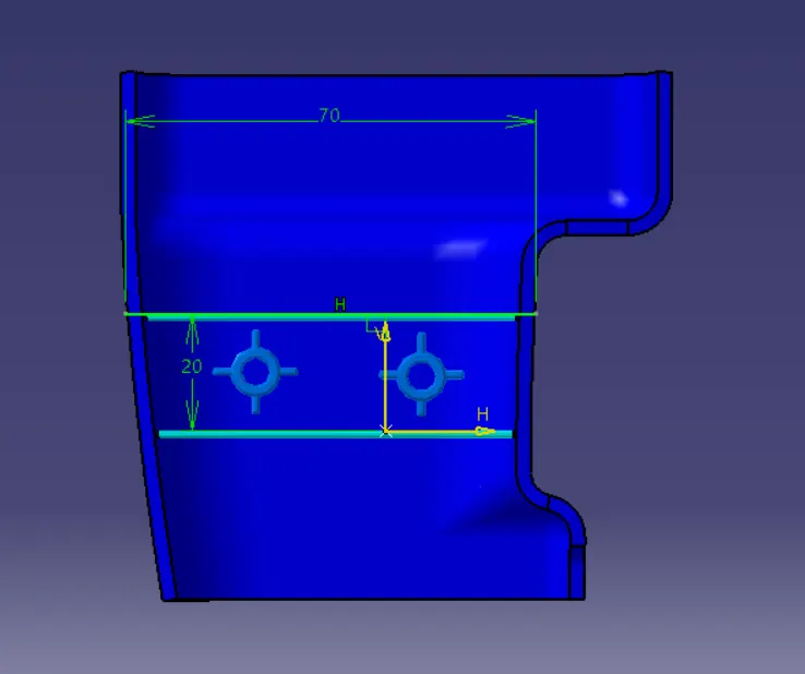
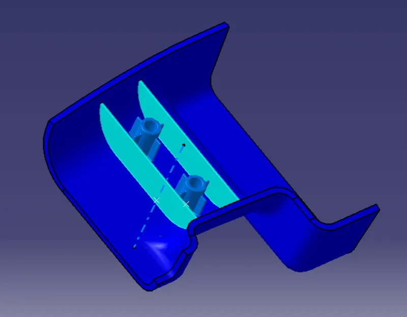
To create the ribs on the solid part body, we need to follow the above-mentioned design guidelines. Initially, I create a line sketch for the rib and I
extruded it in the tooling axis direction and I thicken the extruded surface to 1mm toward the inside,after thickening the extruded surface I gave
0.5deg of draft angle to the rib, and I union trim the rib with the part body to remove the extra surface of the rib, by union trimming the rib with
the part body the rib gets added to the main part body without the unwanted extra part. After adding the rib to the part body, I gave the fillet to
the rib with a radius of 0.25mm (as per the design parameters 0.25mm is the maximum fillet radius). In the same way, I created the rib-2.
RIB 1 AND 2 SKETCHES
RIB ROOT THICKNESS
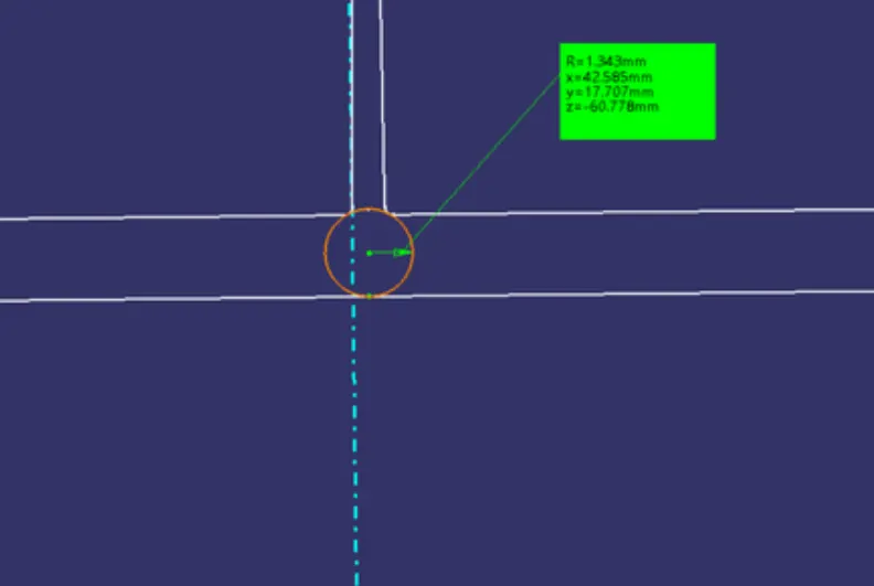
To check the rib root thickness, I created a plane which is perpendicular to the base surface (if the plane is parallel to the base surface the
intersection will be taken, but we can't see any rib intersection on it, so that is why the plane is created perpendicular to the base surface). After
taking the intersection for the body and plane, we need to create a tri-tangental circle at the bottom of the rib. To create the circle, we need to
extract the faces of the intersection (if we directly select the faces without extracting the required faces the input may take the entire intersection
surface as an input) which we need to give as input for the tri-tangental circle. The tri-tangental circle is shown below, with the measurement of it.
SCREW BOSS DESIGN
To create the screw boss, I created the circular sketch in the sketcher workbench and I padded the sketch to 12.5mm. Now, I drafted the inside
and outside surfaces with 0.5deg in the tooling axis direction. After creating the screw boss, I gave 0.25mm of the fillet to all sides. Now, I
translated the screw boss toward the right side for 35mm. To keep the screw boss stiff and rigid, I created 4 supporting ribs for each screw boss.
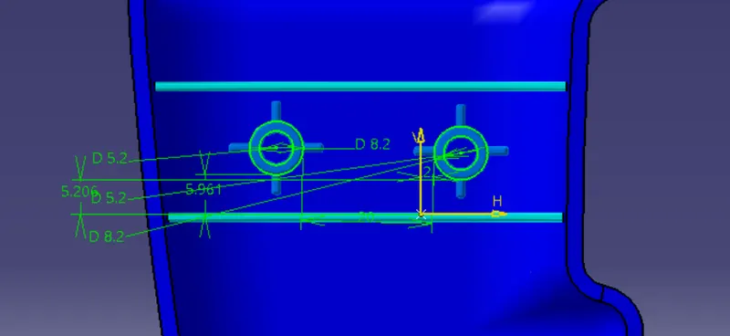
FINAL DESIGN
DRAFT ANALYSIS FOR FINAL BODY
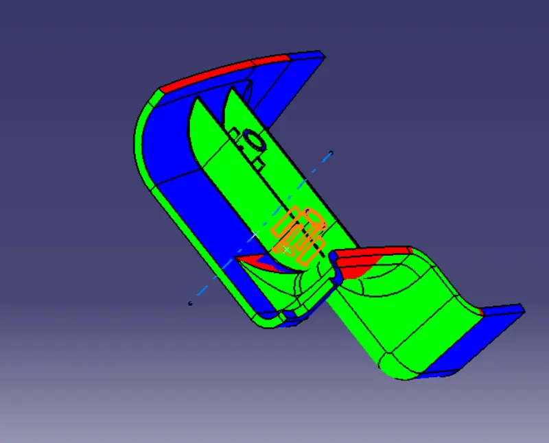
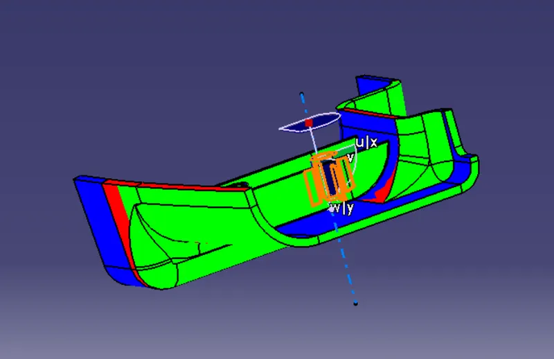
To perform the draft analysis for the solid part body (which has ribs and screw bosses on it), I used the featured draft analysis tool in the
generative shape design workbench. Initially, I aligned the compass to the tooling axis and I selected the solid part body, I gave a 0.9deg draft
angle in the colour bar. If I gave a 3deg draft angle in the colour bar some faces are not clearing properly, due to the class A surface draft angle
and curvatures on the bottom area the solid body has shown in red and cyan colours even though we gave 0.9 deg in the draft angle in the colour
bar we can't decrease the draft angle to less than 05deg because the draft angle for the plastic component is 0.5deg to 3deg).
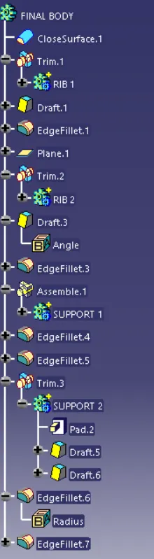
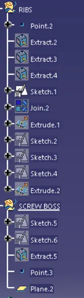
TREE STRUCTURE OF BODY
3D VIEWS OF THE BODY
ISOMETRIC VIEW
FRONT VIEW
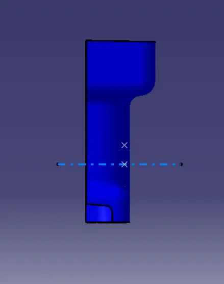
SIDE VIEW
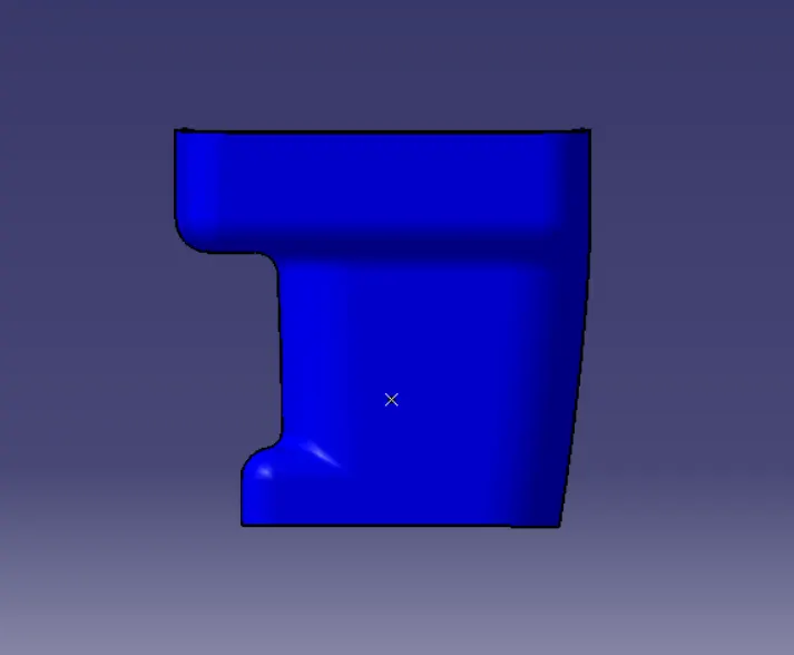
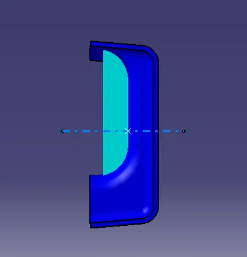
TOP VIEW
CONCLUSION
The main objective of this challenge is to create the B-side features RIBs and Screw Bosses for a given drill handle.THE GIVEN OBJECTIVE IS
COMPLETED