Week 9 - Attachment Feature Creation (Ribs & Screw Boss) - Challenge 1
AIM:
Create Drill Handle with Ribs & Screw Boss
OBJECTIVES:
- Create the rib for the Drill Handle considering the design rules
- Create the Screw boss for the Drill Handle considering the design rules
Introduction:
CLASS-A SURFACE: a surface made by the designer which is given as an input to the plastic modeler to work on. It is an aesthetic surface and the outermost surface.
CLASS-B SURFACE: a surface below a certain thickness from the class-A surface is a class-B surface. This is the surface that contains engineering aspects of a model.
CLASS-C SURFACE: a surface that joins class-A and class-B surfaces is a class-C surface.
Tooling axis: the direction in which the mold opens or the core cavity opens. By providing a tooling axis to the component we can perform the draft analysis of the component.
Design procedure:
- Checking Class A input for imperfections.
- Ensure that the class A surface has no gaps and no discontinuities of the surfaces using the boundary command.
Tooling axis Creation
In injection molding, the Class A surface is first analyzed to determine the axis or tooling direction that separates the molds. Tooling direction is critical for plastic product design because it determines mold direction
Creation Of Tooling Axis
- The tooling axis is created by selecting one of the natural axes as it clears the draft.
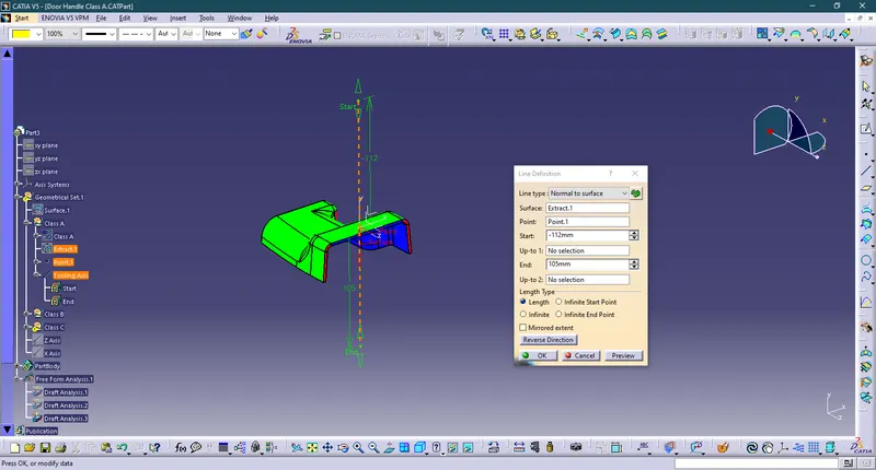
- Here, the tooling axis is created by extracting one of the surfaces for creating a point and a new axis is created at that point.
- So, a flat face is extracted and created a point at its center. Axis is also created at that point
- Now, the line is created using the line tool and giving line type as point-direction and selected the point and direction for creating tooling axis and tooling axis is created along the x direction.
Creation Of Class A Surface
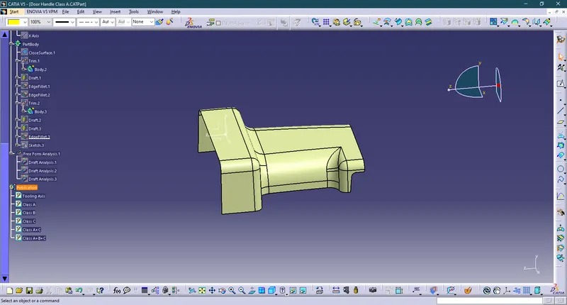
- Class A surface is obtained as the input.
- Join all the surfaces to obtain Class A surface if different surfaces are given as input and ensure no gap is present between any surfaces. Thus, Class A surface is obtained and published. Here, the provided surface is completely joined and can be taken as a class A surface.
Creation Of Class B Surface
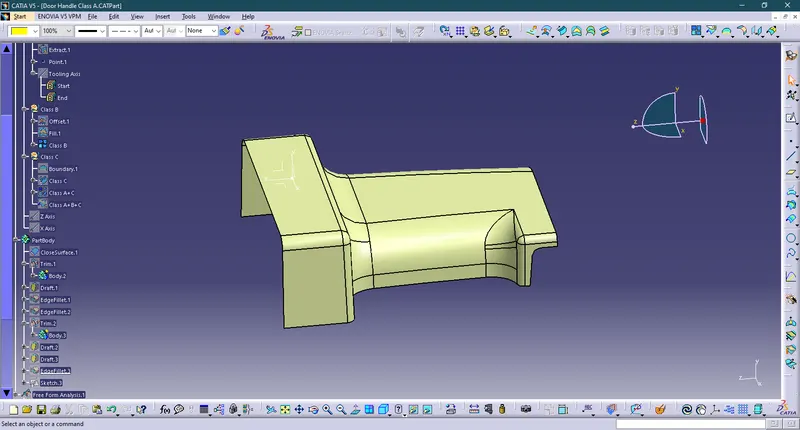
- In this component Creation of the class B surface first, we have to offset the entire model by 2.5m inward some of the surfaces give offset error and ask for offset without these subelements click okay and work on the incomplete surfaces by using the multi-section surface command, sweep and different commands used to complete the class B surface.
Creation Of Class C Surface
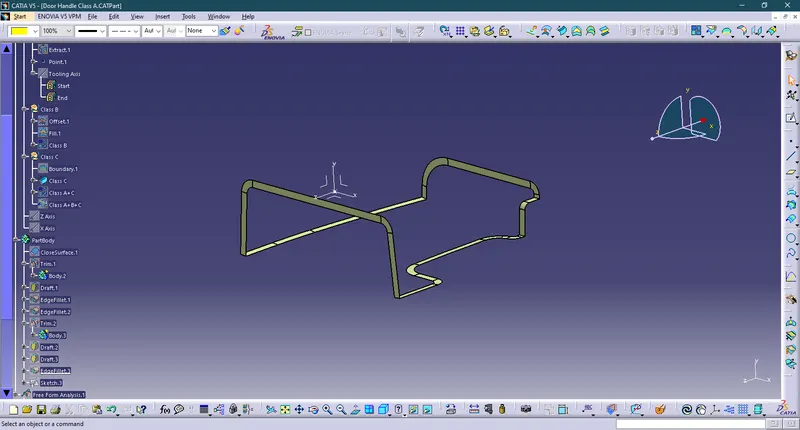
- We first extract the edges from the Class A surface with the help of the multi-extract or boundary command which we create the path for a sweep for class C.like this, we have to create all separate sweeps and join them together. once all the sweeps are joined together we created a class c surface.
Creation of Ribs
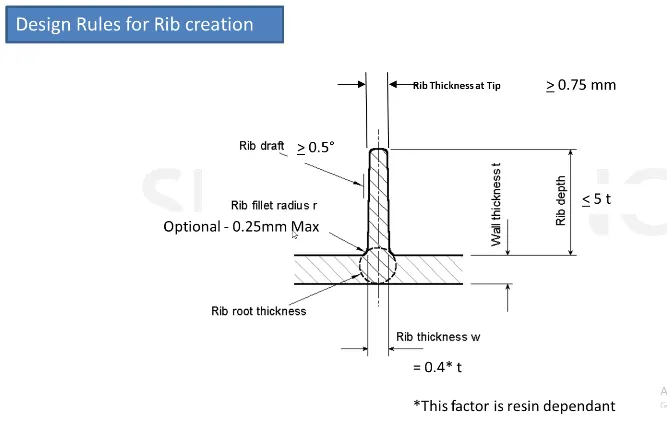
Ribs are indispensable functional structures on many plastic parts. It can effectively improve the rigidity and strength of plastic parts like the H beam. By using ribs, it is not necessary to greatly increase the wall thickness of the plastic parts, and ribs are not undercut structures like the H beam whose structure will be difficult to make for plastic injection molding.
We have made ribs by considering all design requirements
Rib thickness = 0.4*t = 0.4*2.5 = 10mm
Rib Draft = 0.5 deg
Rib fillet radius = 0.25mm
Rib depth = 5*t = 5*2.5 = 12.5mm
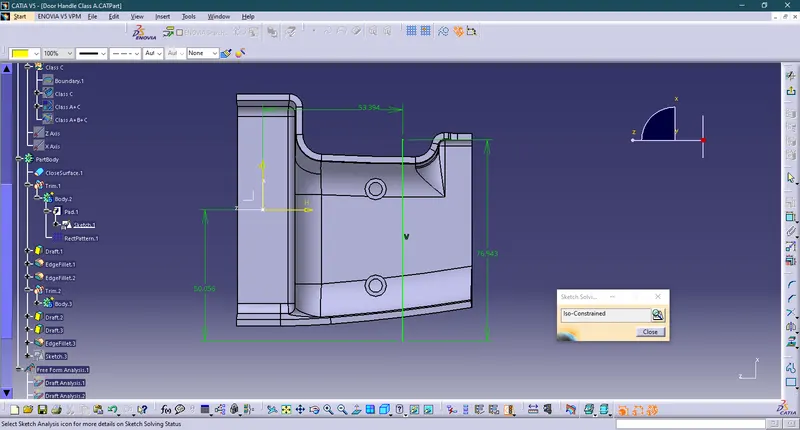
To create the ribs on the solid part body, we need to follow the above-mentioned design guidelines. Initially, I created a line sketch for the rib and I extruded it in the tooling axis direction and I thicken the extruded surface to 1mm toward the inside, after thickening the extruded surface I gave 0.5deg of draft angle to the rib, and I union trim the rib with the part body to remove the extra surface of the rib, by union trimming the rib with the part body the rib gets added to the main part body without the unwanted extra part. After adding the rib to the part body, I gave the fillet to the rib with a radius of 0.25mm (as per the design parameters 0.25mm is the maximum fillet radius). In the same way, I created the rib-2.
Creation of Screw Boss
Screw Boss features are commonly found in injection molding designs. They are used to aid in the assembly of molded parts by providing a channel for a screw. Their primary use is to strengthen holes or slots in the surface present in the part model.
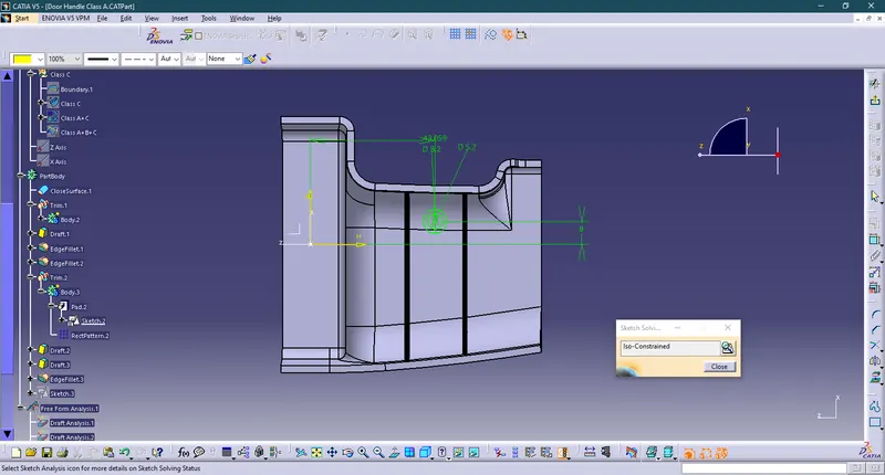
To create the screw boss, I created the circular sketch in the sketcher workbench and I padded the sketch to 12.5mm. Now, I drafted the inside and outside surfaces with 0.5deg in the tooling axis direction. After creating the screw boss, I gave 0.25mm of the fillet to all sides.
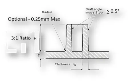
General Guidelines for Bosses:
- Draft - 0.5 degrees on the walls of boss
- Thickness - Typically 40%* of the nominal wall at the base.
- Height to Diameter Ratio - 3:1
- Radii - 0.25mm maximum radii.
- Height = 12.5mm
- Outer Diameter = 8.2
- Inner Diameter = 5.2

Rib Root Thickness Analysis
The value of rib root thickness must be within 30% greater than the wall thickness
In this case, the wall thickness is 2.5 mm and so the maximum limit is 3.25 mm. So our rib root thickness is within the limit.
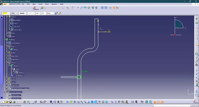
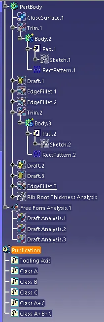
Tree Structure
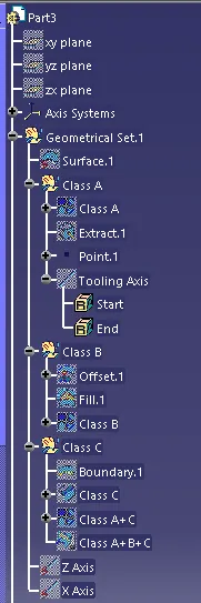
Surface Part
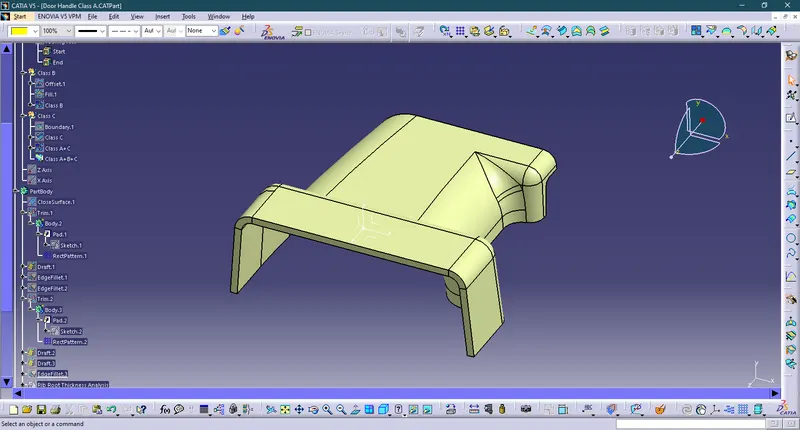
Solid Part
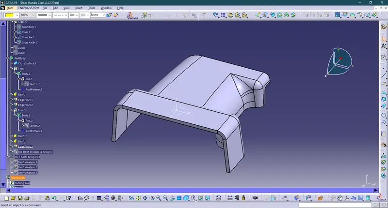
Isometric
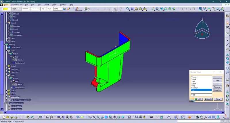
Front
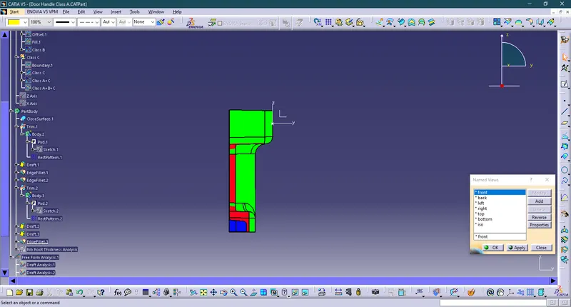
Left
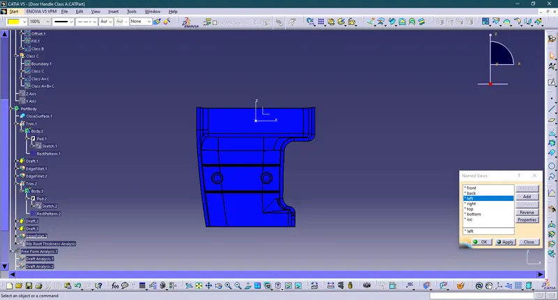
Right
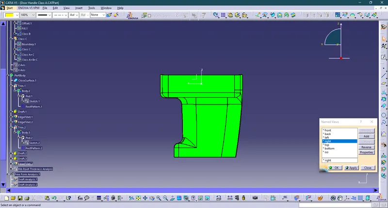
Top
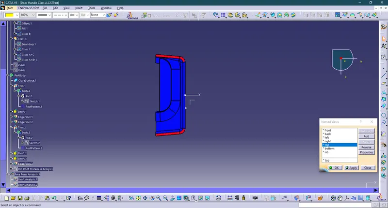
Bottom
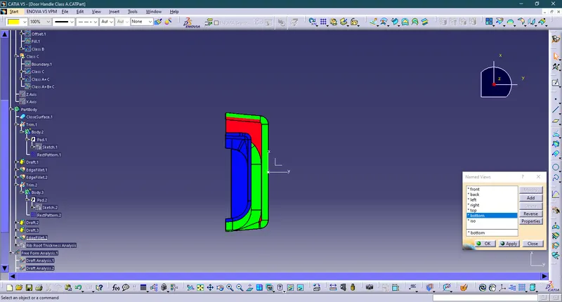
A detailed report on draft analysis and the tooling axis creation.
DRAFT ANALYSIS
- For molded or cast parts, the draft angle is the amount of taper perpendicular to the parting line. It is measurable in degrees. Because plastic shrinks and sticks on molding surfaces as it cools, we draft the walls of the plastic part so that it ejects or breaks free from the molding surfaces more easily and without dragging. To reduce the risk of damage to the parts and ensure ejection, a functional injection molding part must have drafts on both the cavity and core sides
Nominal values for Draft angles
- 3 Degrees is a nominal draft angle
- 5 Degrees can also be manufactured. Increasing the manufacturing cost
- 7 Degrees is considered for Textured surface parts
Importance of Draft in injection molding
- Reduces the possibility of part damage due to friction during the release
- Reduces mold wear and tear
- Ensures a uniform, smooth, unscratched finish
- Ensures the integrity and uniformity of other surface finishes and textures
- Reduces overall cooling time by reducing or eliminating the need for unusual ejection setups
Steps followed for Draft Analysis
- The created part must be changed to the material mode in the display frame
- Compass is enabled and placed in the direction of the Tooling Axis
- The lock command is then used to fix the compass along the tooling axis
- Colour codes are classified and Draft angle is applied
- Running point analysis is used to display permissible draft angle
Class A Surface Draft Analysis
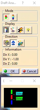
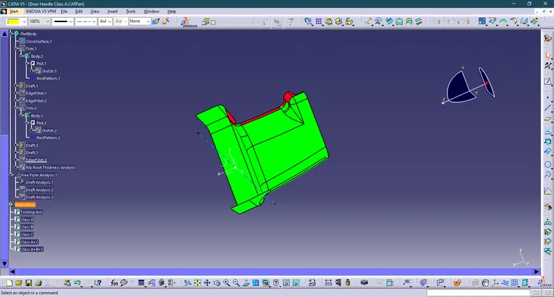
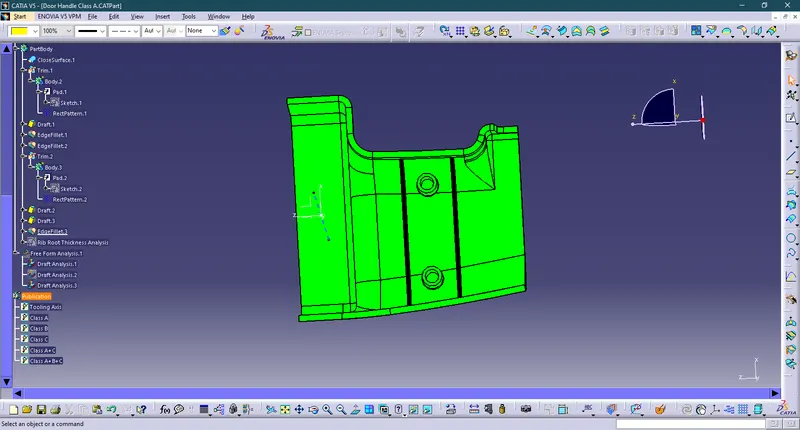
In Class A surface draft analysis we can see that most of the surface is green and some surface is red so we can say that the tooling axis that we have created is correct as well as the component can be easily ejected.
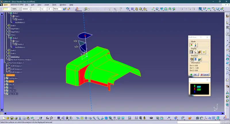
Closed Surface Analysis
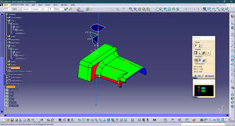
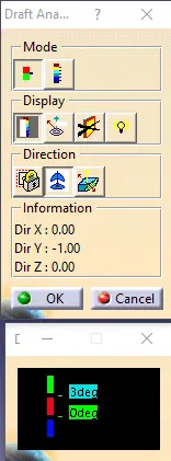
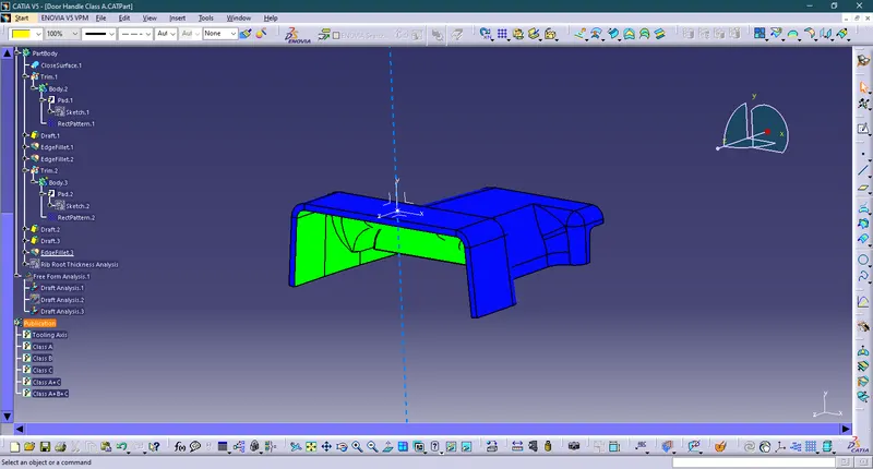
In closed surface analysis, we can see that Class A surface is Green, and Class B and Class C surface is Blue. Class C Surface is blue because we have given a 90 deg Sweep. And We can see that the Class A surface is green so that's why we can easily eject our product.
Draft Analysis of Class B features
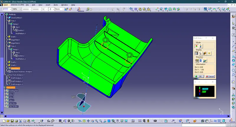
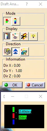
The draft for both rib and screw boss is 0.5 but there might be some change in draft angle at some of the points so we take 0.49 degrees for analysis. Draft more than 0.49 degrees shown as green. The draft below 0 degrees is shown as blue. Draft between 0 and 3 degrees shown as red.
Conclusion :
Hence we have created a Drill Handle through the given class A surface and created the required Tooling axis and performed the Draft analysis on the model and also for the solid model. so this Draft analysis feature is very useful to check the Draft angle and can check whether this part makes any problem while manufacturing that product. And the nominal Drafting angle is 3 Degree so we need to design the part with a minimum of 3 Degree has the Draft. We have done a Draft Analysis of Class B features and as we can see it is all green so we can easily manufacture such components.