Week 9 - Attachment Feature Creation (Ribs & Screw Boss) - Challenge 1
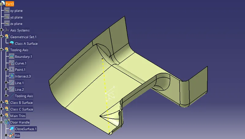
1. CREATING TOOLING AXIS
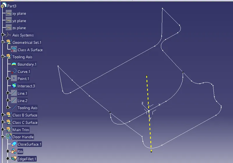
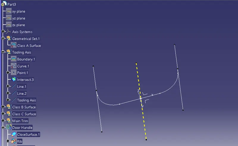
- Create bisecting line with the two lines and point to create a tooling axis.
- BISECTING LINES were used to get the exact medium from the two sides
- The tooling axis is created for the component by bisecting two axis from x and y planes.
2. DRAFT ANALYSIS
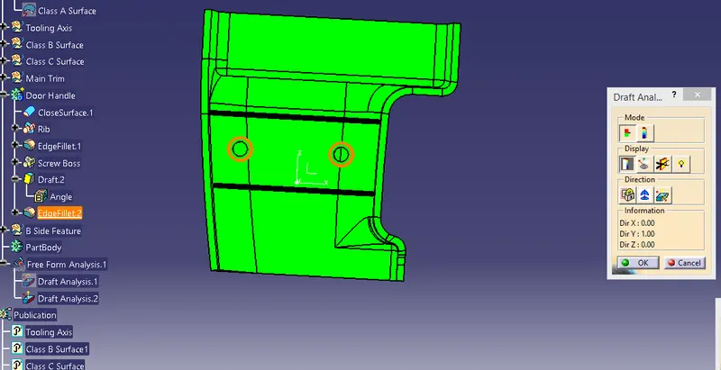
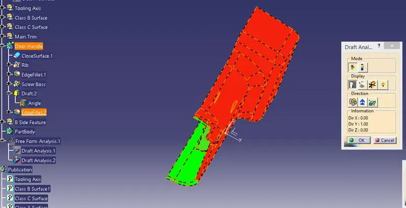
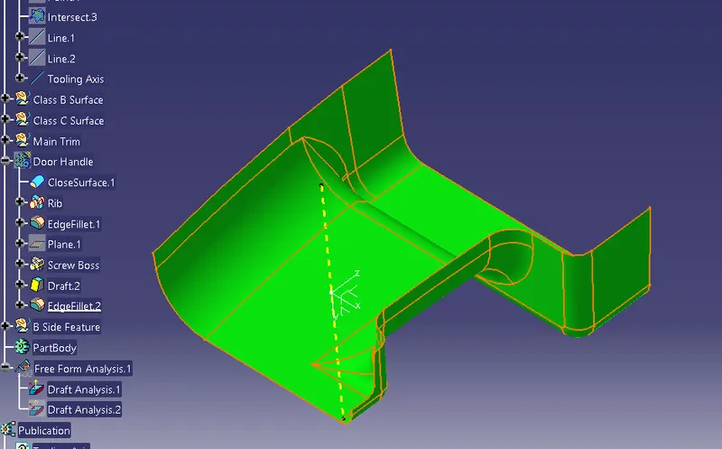
- For draft analyses go to insert > analysis > feature draft analysis.
- Use the compasss to define the draft direction.
- In the colour scale change the draft angle to 3 degree.
- The component changes to green in indication of passing draft angle.
- Use running point to check the angle on the component
3. B Side feature creation
Rib Creation:
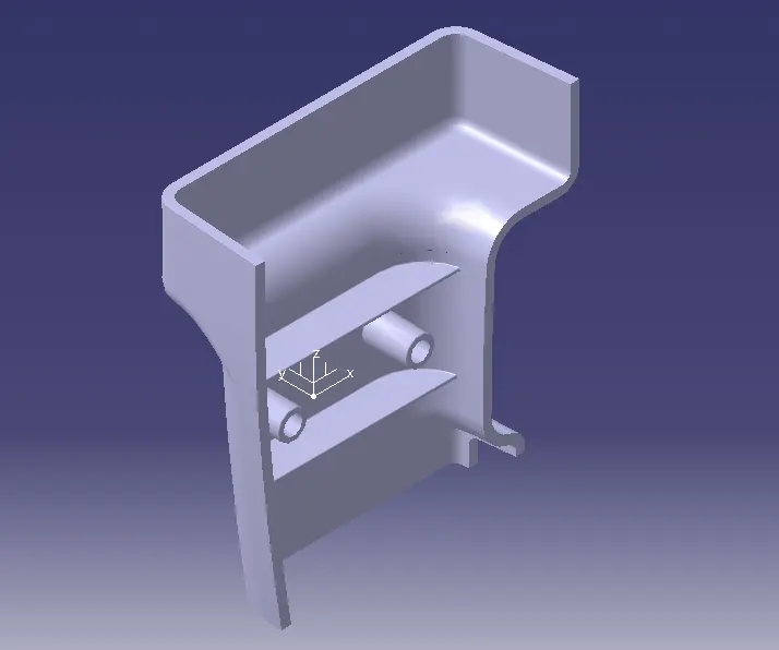
First, the base surface where the rib has to be created is extracted using the Extract command. A positioned sketch is created and the profile for the rib is drawn.
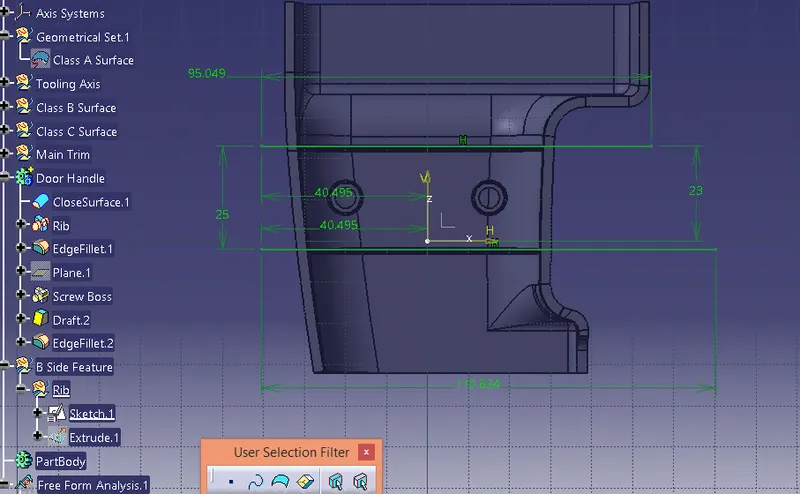
The profile is extruded, to find the height,h=Wall thickness * 5
i.e, 2.5*5 = 12.5 mm
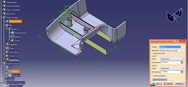
The extruded surface is thickened,
Thickness,w=0.4*t
i.e, 0.4 2.5 =1mm
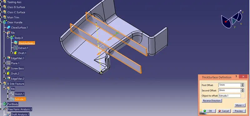
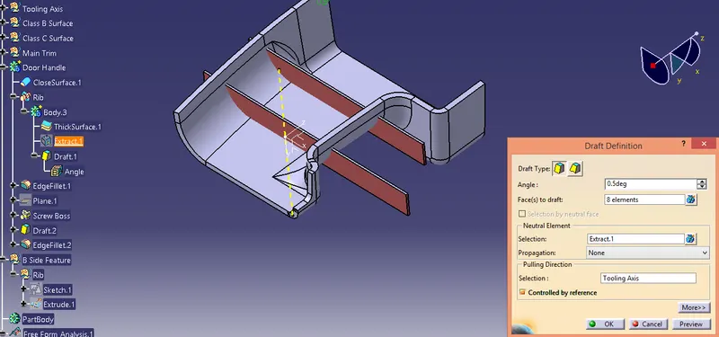
The draft is applied to the sides of the ribs. As per the design rule, the ideal draft angle is 0.5 deg
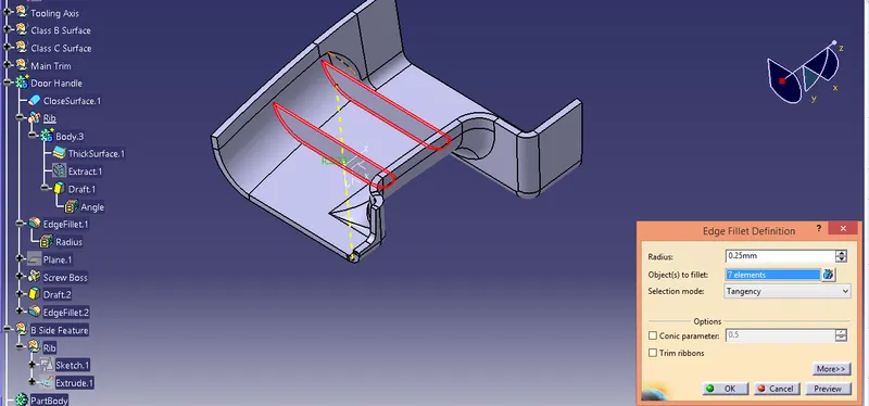
Then fillet is applied to the faces of the rib. As per the design rule, the fillet can be 0.25 mm.
CREATING THE SCREW BOSS
Screw Boss features are commonly found in injection molding designs. They are used to aid in the assembly of molded parts by providing a channel for a screw. Their primary use is to strengthen holes or slots in the surface present in the part model.
We have considered the size of the screw boss as M06.
Thickness,w=0.6*T
=0.6*2.5
=1.5 mm
Therefore, the thickness of the boss can be 1.5 mm per side.
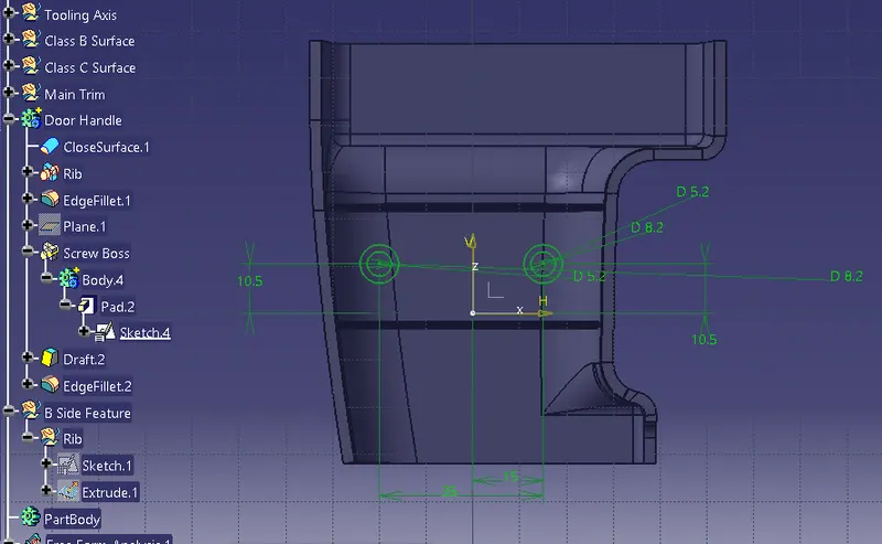
Once the sketch is completed, then it is padded using the Pad'command. The height to diameter ratio can be 3:1
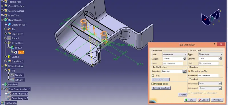
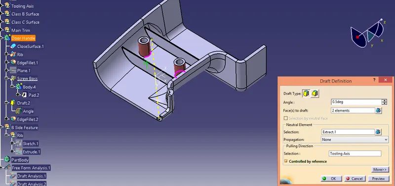
Next, the draft is given to the boss. As per the design rule, the draft given for screw boss is 0.5 deg.
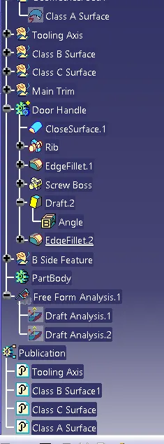
Tree Structure
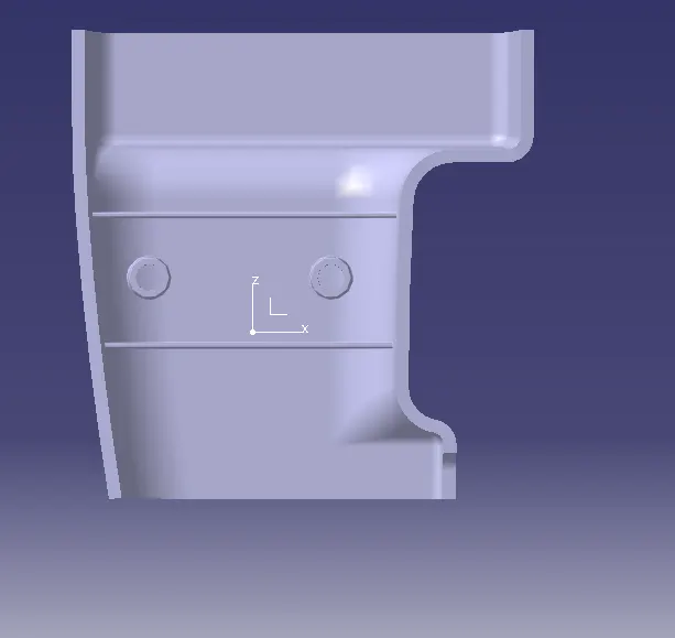
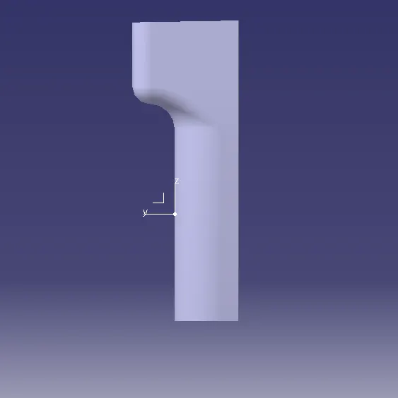
Views
4. Draft Analysis