Week 9 - Attachment Feature Creation (Ribs & Screw Boss) - Challenge 1
A) AIM :- Create Rib and Screw boss for the door handle considering design rules
B) INPUT :- Given Class A surface of door handle with the thickness of the component 2.5 mm.
C) Procedure for the projects :-
- Creating the tooling axis
- Draft analysis of Class A surface
- Creating Class B surface
- Creating Class C surface
- Surface and solid body
- Draft analysis of Solid body
- Engineering features Rib and Screw boss
- Draft analysis of Solid body with engineering features
D) CREATION OF TOOLING AXIS :-
1. FIRST CREATE A POINT ON THE CENTRE OF GRAVITY OF DOOR HANDLE USING MEASURE INERTIA IN WHICH CREATE GEOMETRY.
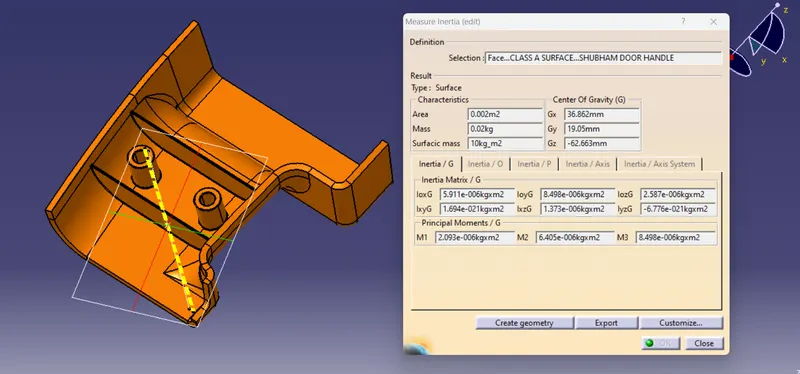
2. CREATE A LINE AT THAT POINT IN Y DIRECTION AND THEN PERFORM DRAFT ANALYSIS BY COINCIDING THE COMPASS TO DUMMY TOOLING AXIS .
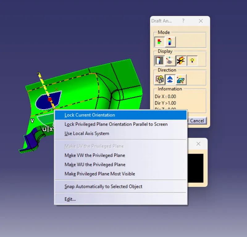
3. DOUBLE CLICK ON THE CENTRE LINE OF THE COMPASS AND CHANGE THE ORIENTATION OF U ,V TO 1 DEGREE AND SIMPLY CHECK WHERE ALL THE FACES OF THE MODEL IS CLEARING BY ROTATING U AND V.
4. LOCK THE COMPASS DIRECTION AND CREATE A LINE WITH POINT 1 AND COMPASS DIRECTION AS SHOWN IN FIGURE .
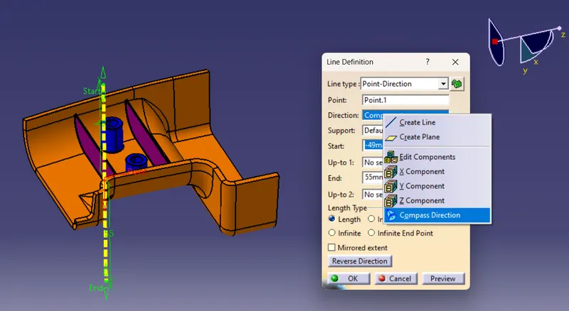
5. COLOUR IT YELLOW AND PUBLISH THE TOOLING AXIS.
E) Draft methodology Flowchart :-
| 1. | CHECK CONNECTIVITY |
| 2. | FIND TOOLING AXIS |
| 3. | PUBLICATION AXIS AND MODEL |
| 4. | DEFINE MATERIAL |
| 5. | FIX AND LOCK COMPASS |
| 6. | MEASURE DRAFT ANGLE |
F) Features used for design A-Class, B-Class, and C-Class :-
- Line
- Point
- Axis system
- Extrude
- untrim
- extrapolate
- Extract
- boundary
- Join
- Swept
- fillet
- close surface
- Intersecting
- publication
- Draft analysis
G) Procedure for design A-Class, B-Class, and C-Class of DOOR HANDLE :-
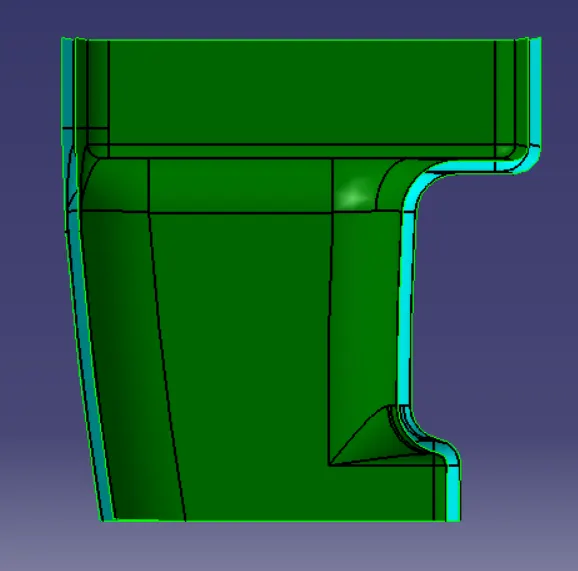
- OFFSET THE GIVEN CLASS A SURFACE OF DOOR HANDLE AT 2.5MM.
- FILL THE PATCHES WHICH WERE MISSED AFTER OFFSET USING SURFACE FILL COMMAND..
- SWEPT CLASS A SURFACE TO 93-DEGREE WITH REFERENCE SURFACES IN APPROPRIATE DIRECTION.
- JOIN SWEPT SURFACE AND CLASS A AND THEN TRIM IT WITH CLASS B SURFACE.
- CHANGE INTO CLOSED BODY FOR APPROPRIATE OUTPUT.
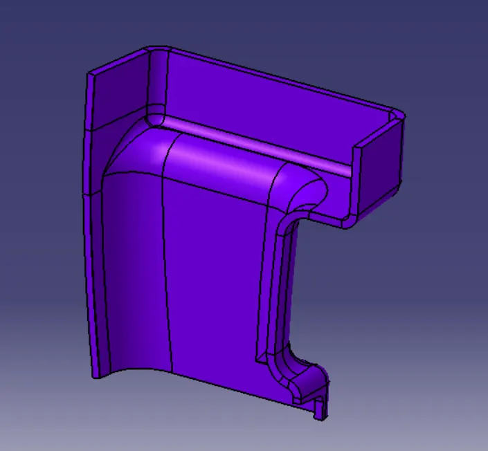
H) A-Class Surface with tooling axis , Class A surface with draft analysis :-
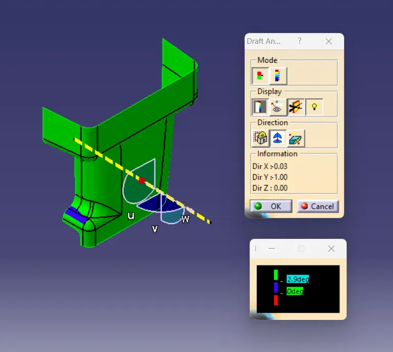
In the draft analysis of Class A surface of door handle, most of surface are green that means the surface has draft angle more than 2.9 degree and some surface has draft angle in between 3 to 1 degree which is shown in blue color and there is not negative draft surface here.
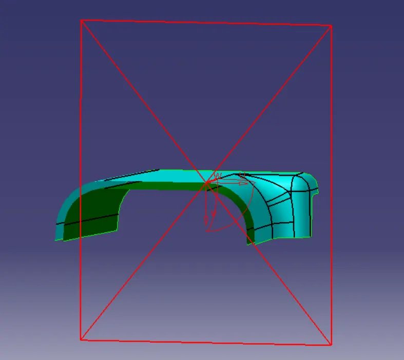
I) B-Class Surface with 2.5 mm offset and Sectional View :-
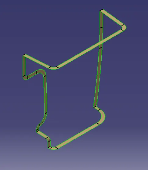
J) C-Class Surface without Final Trim :-
K) Final Output after trim C-Class with B-Class :-
L) Procedure for Features Draft Analysis :-
- Before performing the draft analysis we create the Main tooling axis then the procedure.
- {Go to menu bar > select insert > Analysis > Feature Draft Analysis} .
- Now, align the compass z-direction with the main tooling axis which we created in the previous steps.
- Now, open the color scale and enter the value as 3 deg.
- Now hover the cursor over the body to check if every face has an angle greater than the given angle.
- Also, if the whole body is in green color it means that the value at all the faces is greater than the provided angle.
M) Creation of Engineering features :-
1. Rib :-
Rib provides an economical way to increase stiffness and strength to the mould parts without increasing the overall thickness of the wall. It is thin protrusion that extended perpendicular from the wall.
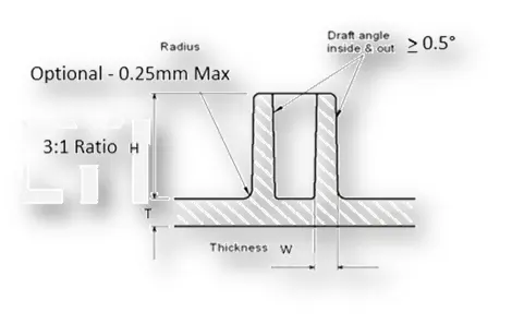
Design considersation of the Rib
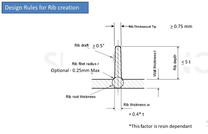
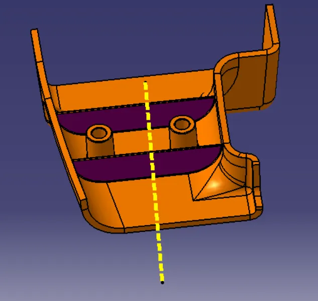
Screenshot of both Rib :-
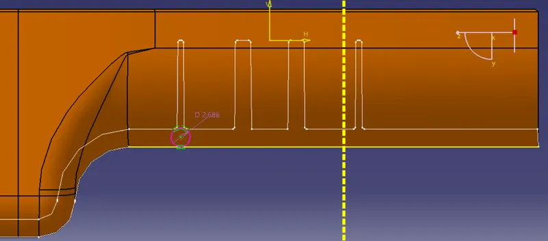
Rib root thickness analysis :-
To check the Rib root thickness, first take perpendicular intersection across the body and the Rib and then have to sketch a circle which tangent to the Rib base or root area by using tritangent type circle. The value must be within 30% greater of the wall thickness.
2) Screw Boss :-
Screw boss are used as a point for attachment and assembly, most common in as cylindrical projection with hole design to receive screw or other types of fastening hardware.
Design considersation of the Screw boss
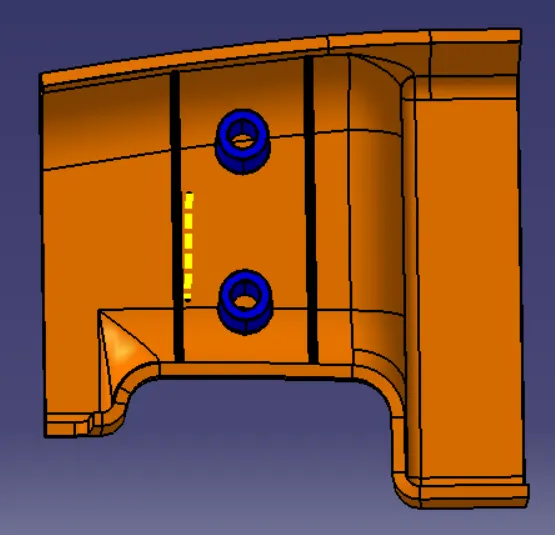
Screenshot of Screw Boss :-
N) Screenshots of the Draft analysis report for the given final plastic component with rib and screw boss :-
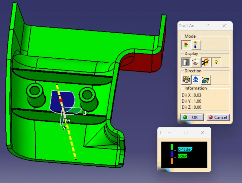
The draft analysis at draft angle 0.45 degree with the tooling axis to the plastic componenets engineering feartures like Rib and Screw boss show green which means it clear during production process, but some surface of left side of Class-C surface has negative draft (-0.6 to -0.8 degree) which show in red color.
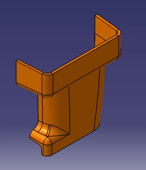
O) Screenshots of the completed design in various orientations :-
- Isometric View :-
- Front View :-
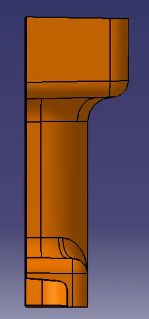
- Side view :-
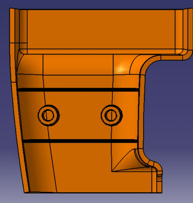
- Top View :-
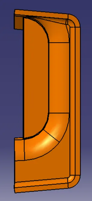
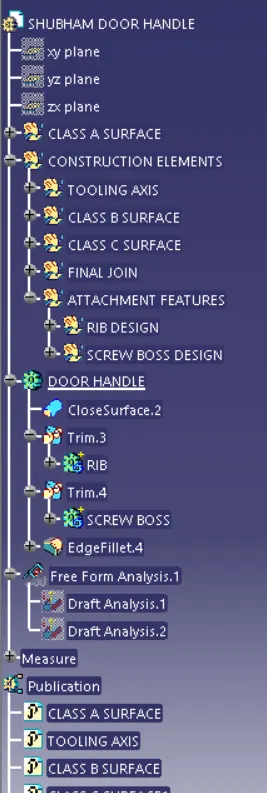
P) Tree structure of Door handle :-