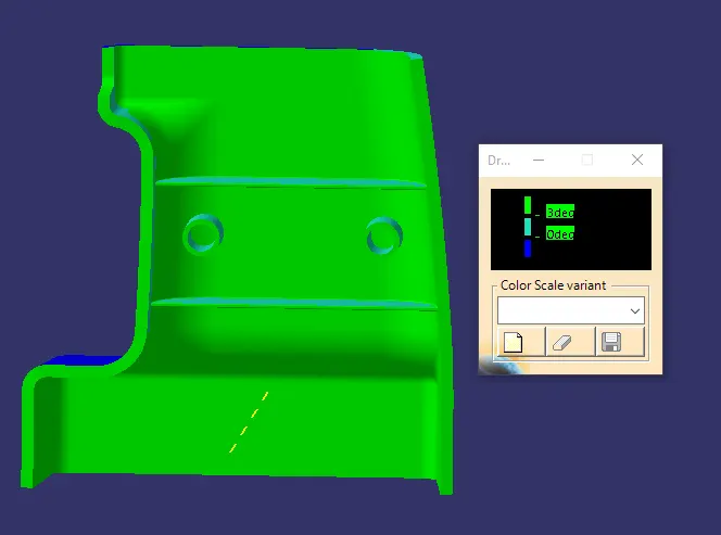
Week 9 - Attachment Feature Creation (Ribs & Screw Boss) - Challenge 1
Attachment Feature Creation (Ribs & Screw Boss) in Door Handle
Tooling Axis creation:
It is defined as the direction in which the mould/core and cavity open. Selection of the direction of the tooling axis depends on the ease at which components can be easily ejected.
Class A Surface:
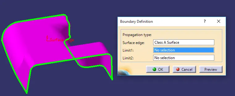
- Check for gaps between surfaces for that click on join and then preview.
- If theres any gap between the surfaces join them with a maximum tolerance of 0.003 mm.
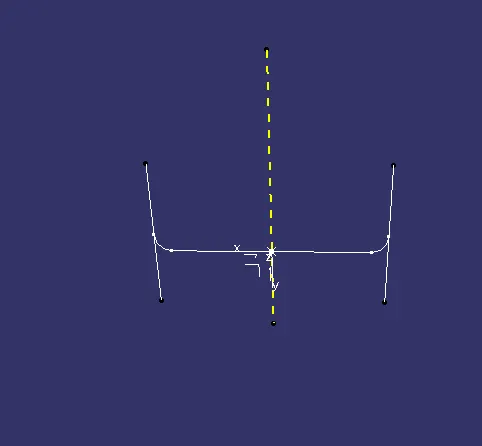
- Intersect the yz plane with respect to the class A surface.
- Hide the class A surface and create point to point lines on the suspected drafts.
- Create bisecting line with the two lines and point to create a tooling axis.
- BISECTING LINES were used to get the exact medium from the two sides so that maximum positive draft angle can be achieved.
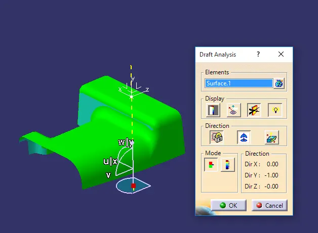
Draft Analysis
CLASS B SURFACE:
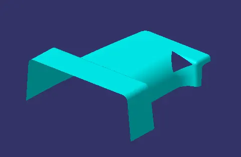
- Take a 2.5mm Offset from Class A Surface upward towards the unfinished surface we get .
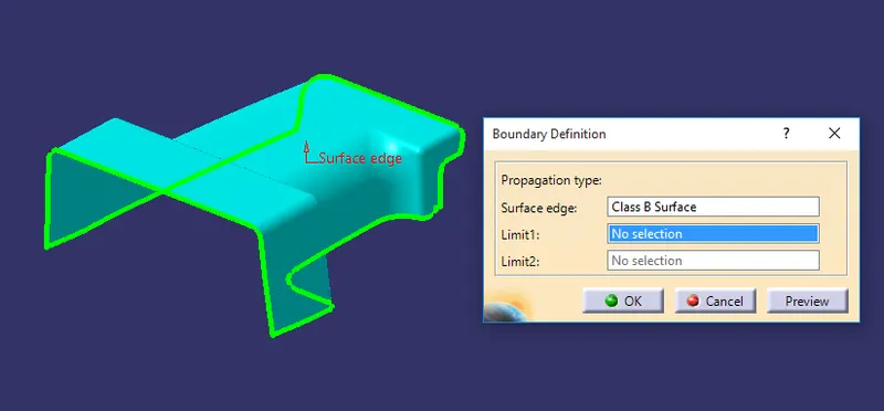
- Use a commands like multi section surface, trim and join to fill it both surfaces, This is Class B Surface.
Class C Surface:
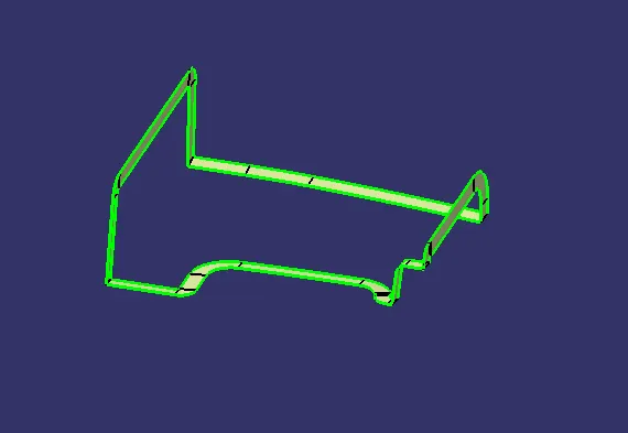
- Unhide the A Surface to Take a boundary as a reference to make C surface.
- Go to sweep line-> with Reference Surface 93 degree draft angle for all sweep.
- And join all the sweep parts to make a Class C surface.
Class C & Class A Surfaces:
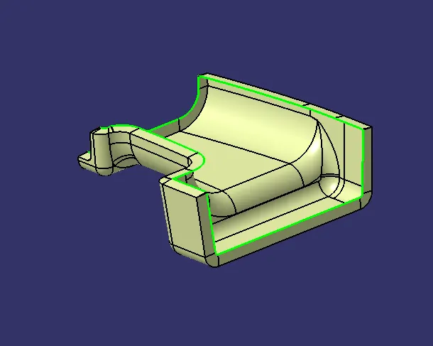
- Join the both finished Class C and Class A surfaces.
- Trim the exces part in B surface with use of joined surface.
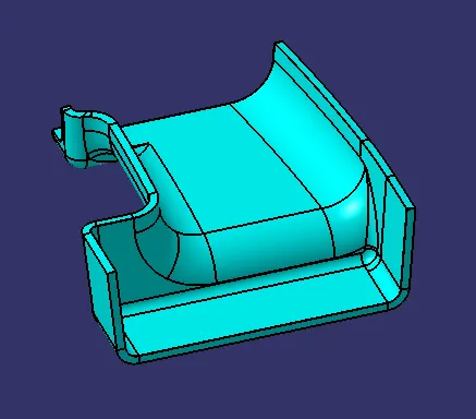
Attachment Feature Creation:
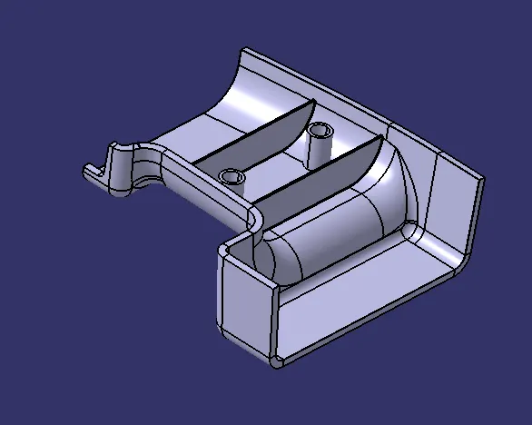
Rib:
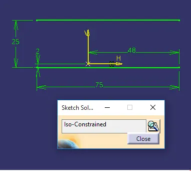
- Extract the base surface where we need and make a sketch 2 parallel lines,
the values I used mentioned the diagram given below.
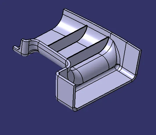
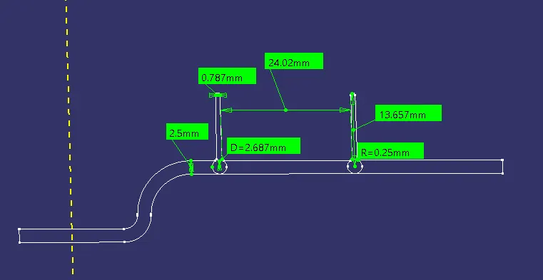
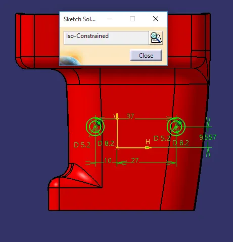
Screw Boss:
- Using a same extract create for ‘Rib’, create a sketch, the measurements are taken by diagram given below.
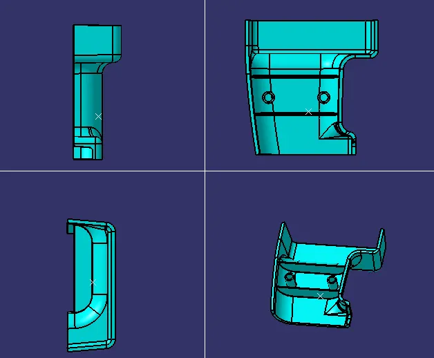
Draft Analysis on feature creation