Week 9 - Attachment Feature Creation (Ribs & Screw Boss) - Challenge 1
RIBS & SCREWBOSS
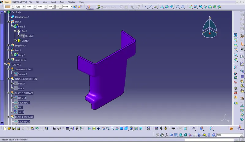
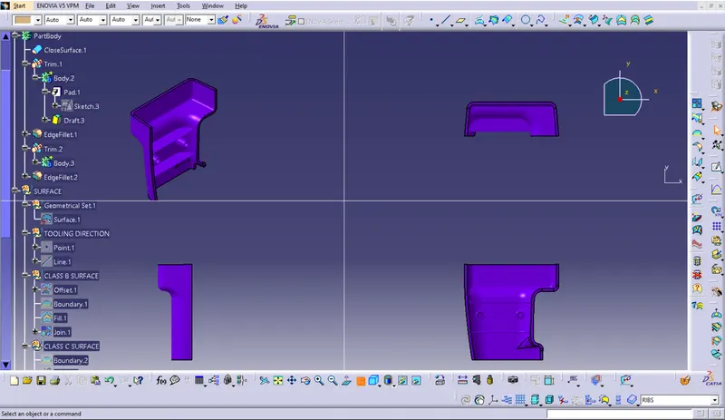
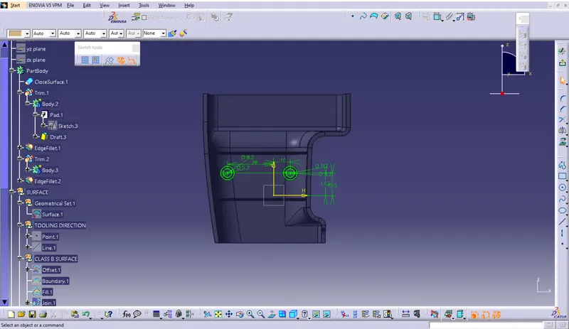
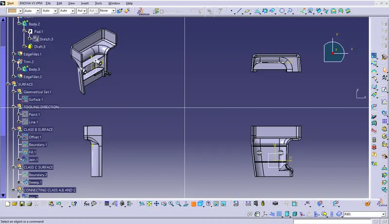
AIM: To make a Ribs and Screwboss from the provided class-A surface.
INTRODUCTION:
Class A surface: A surface made by the designer which is given as an input to the plastic modeler to work on. It is aesthetic surface and the outer most surface.
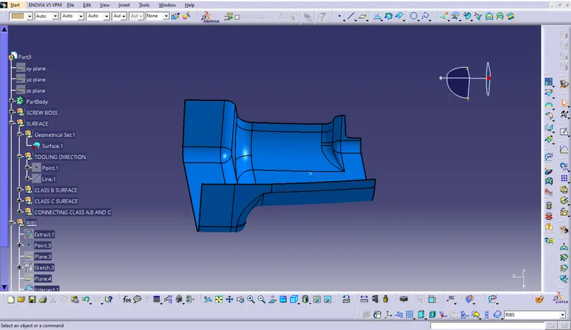
Class B surface: A surface below a certain thickness from the class-A surface is class-B surface. This is the surface that contains engineering aspects of a model.
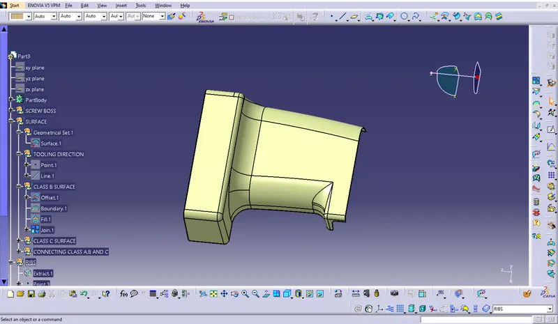
Class C surface: A surface that joins class-A and class-B surfaces is class-C surface.
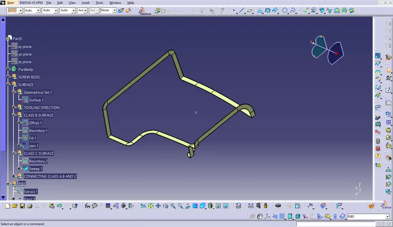
Tooling Direction:
-
It is defined as the direction in which the mould/core and cavity open. Selection of the direction of the tooling axis depends on the ease at which components can be easily ejected.
-
By analysing the component the most easily ejectable direction is somewhere close to the Z direction,(might be inclined to it) so we have made a sketch on the YZ plane of Axis System) to create a bisecting line considering the 2 faces which might be difficult to be tooled.
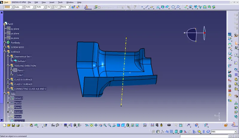
DRAFT ANALYSING:
-
The Draft Analysis allows the user to easily analyze a part for proper draft angle. A Draft Angle describes the amount of taper for molded or cast parts perpendicular to the parting line. Find the Draft Analysis in Tools tab. Draft Analysis is applicable for 3D part models.
-
To create a Draft Analysis for any 3D part file, It needs to:
-
User can change the pull direction the Part/Surface.
-
A panel of gradient specifies a range of deviation from the pull direction. There is provision to change the deviation range and color of the result. With the help of mouse hover user can check draft angle on the component.
-
Select Part/Surface
-
Select the Pull Direction
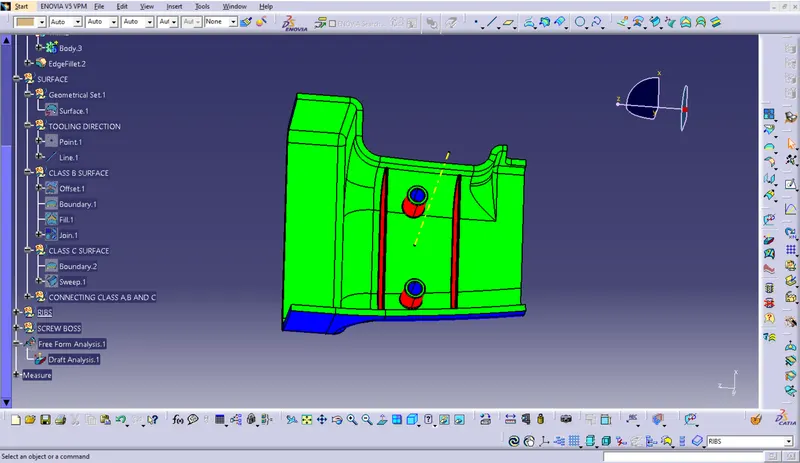
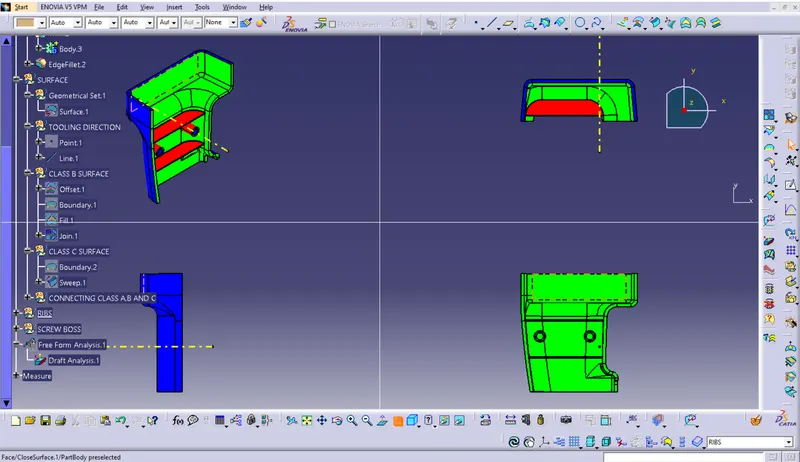
RIBS CREATION:
Step 1
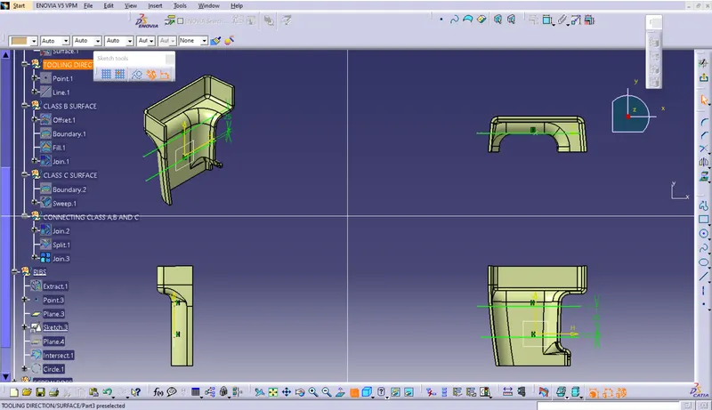
Next, the profile is extruded, to find the height,h=Wall thickness * 5
=2.5*5
= 12.5 mm
Therefore, the height is 12.5 mm
step 2
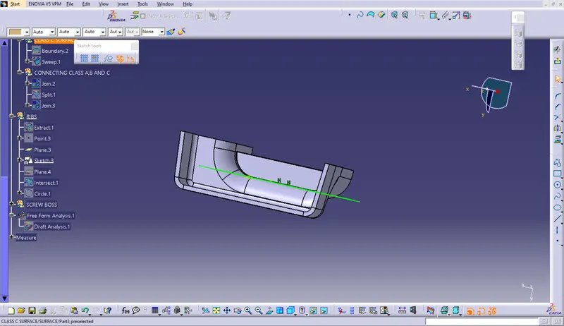
The extruded surface is thickened,
Thickness,w=0.4*t
=0.4 2.5
=1mm
Therefore, the thickness of the rib is 1 mm
also The draft is applied to the sides of the ribs. As per the design rule, the ideal draft angle is 0.5 deg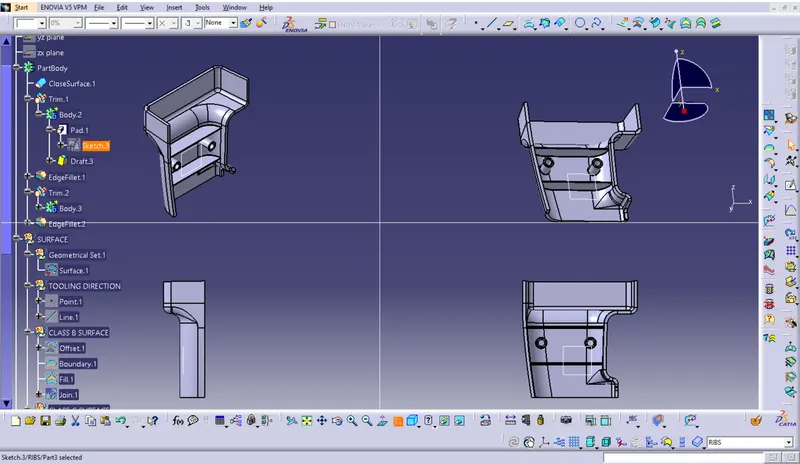
Step 3
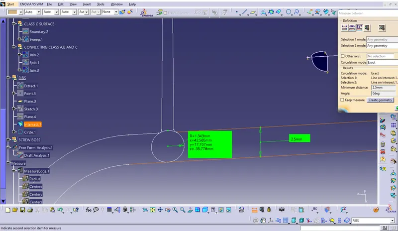
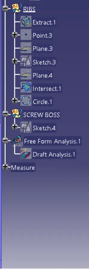
- To check for the Rib root thickness, We have to take an Intersection with the XY plane and the Coin holder component. Once we get to the intersection we have to create a tri-tangent circle at the rib area and measure it. The value must be within 30% greater of the wall thickness.
CREATING SCREW BOSS:
- Screw Boss features are commonly found in injection molding designs. They are used to aid in the assembly of molded parts by providing a channel for a screw. Their primary use is to strengthen holes or slots in the surface present in the part model.
-
For thickness, the design rule is as follows,
Thickness,w=0.6*T
=0.6*2.5
=1.5 mm
- In this case, we have considered the size of the screw boss as M06.
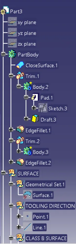
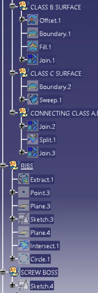
TREE STRUCTURE:
FINAL OUTPUT: