CATIA-Week 9.1 - Attachment Feature Creation (Ribs & Screw Boss)
AIM :
To create the attachment feature (Ribs & Screw Boss) for the door handle.
OBJECTIVE :
- To make sure that the model meets the design rules for rib & screw boss creation.
- To create the Tooling axis
- To perform Draft analysis on the component.
DESIGN METHODOLOGY:
1. TOOLING AXIS CREATION -
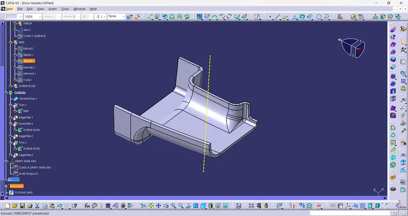
The Tooling Direction is basically the direction that the mold pulls a part. The mold is built in two separate pieces, basically. You have a Cavity side and you have the Core side. The Core pulls apart from the Cavity and that's the Dye line or the Tooling Direction.
- Open the given CAT part file.
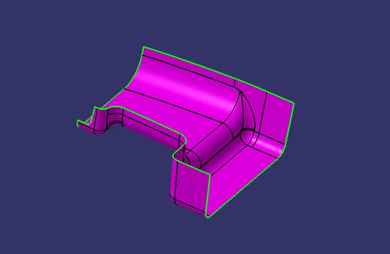
- Check for gaps between surfaces for that click on join and then preview.
- If theres any gap between the surfaces join them with a maximum tolerance of 0.003 mm.
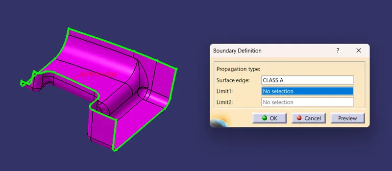
- Extract the boundary and dissemble the boundary.
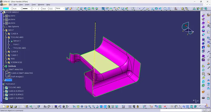
- Find the correct tooling axis where the material don't interfere with the tooling axis and all the elements can be created.
- Extract a surface which is more over a flat type and create a point at the middle and create tooling axis towards Y-direction.
2. PUBLICATION
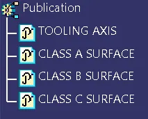
- Publication is done to the component to make it visible and navigate easily.
- To publish the component go to tools > publications and then select the tooling axis and the class A surface.
- A separate tree structure is formed under the main part.
3. DRAFT ANALYSIS
The Draft Analysis command enables you to detect if the part you drafted will be easily removed. This type of analysis is performed based on color ranges identifying zones on the analyzed element where the deviation from the draft direction at any point, corresponds to specified values.
- Before going to drat analysis go to customized view parameter >under mesh >check material and then click ok.
- Now for draft analyses go to insert » analysis » feature draft analysis.
- Use the compasss to define the draft direction.
- In the colour scale change the draft angle to 3 degree.
- The component changes to green in indication of passing draft angle.
- Use running point to check the angle on the component.
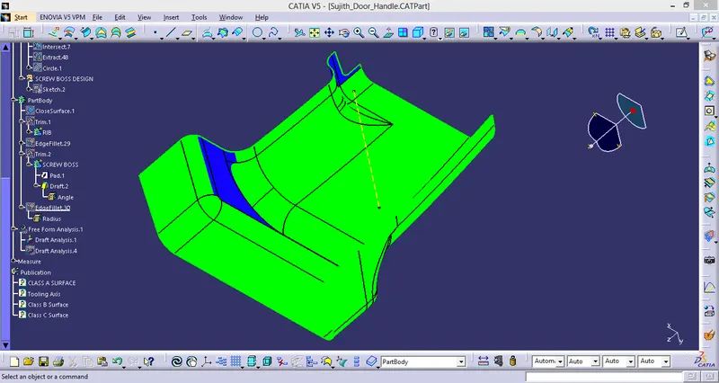
- The draft analysis is complete.
4. CREATING CLASS B SURFACE
- Offset the surfaces to 2.5 mm to create the thickness
- Check whether all the surfaces are properly offsetted.
- One corner does not offsetted, will be created with multi-section command.
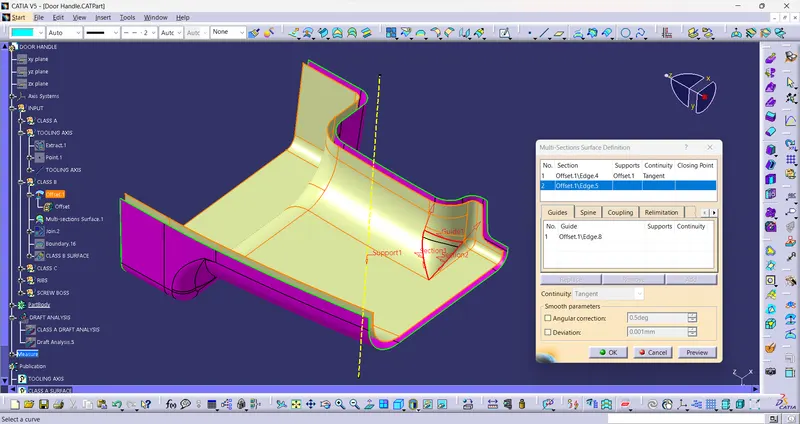
- Join all the surfaces together and class B surface will be created.
- While triming with the class c surface some of parts not getting coinside, will extrapolate 4mm with selecting the outer boundary.
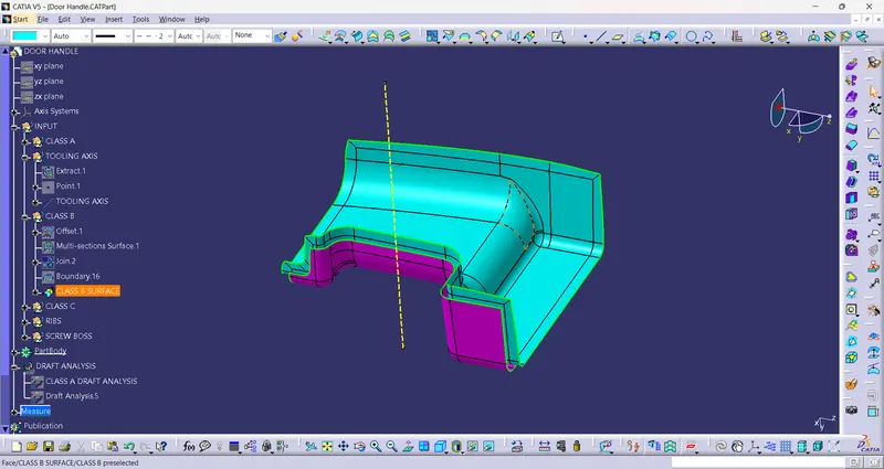
5. CREATING CLASS C SURFACE
- Extract the boundary from the class A surface using boundary command.
- Using disassemble tool to divide the boundary as the boundary contains domains.
- Use sweep command > choose profile type line > subtype as with draft direction > choose guide curve and draft direction > draft angle as 3 degree > preview.
- After getting sweep then trim the output with class B surface to get final output.
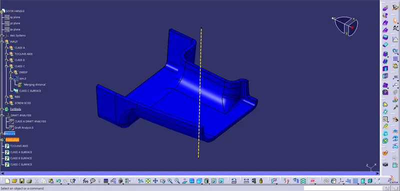
- Now open part design workbench and using close body surface create a solid of the component.
6. B SIDE FEATURES CREATION
RIB CREATION-
- Rib is a feature which provides stiffness and strength to molded parts.
- They are thin extensions that run perpendicular from a wall or plane.
- They provide these features without increasinbg the overall thickness.
- If the wall is too thick, warping and sinking can result so that the entire design may need to be rejected.
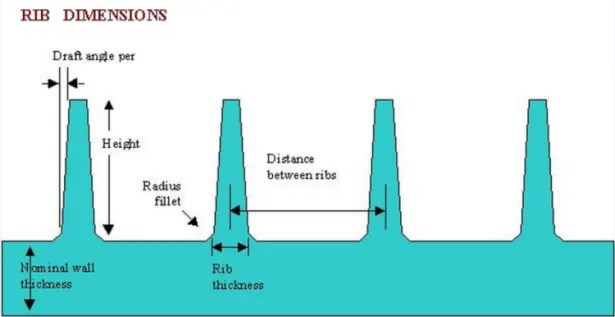
- Design Principle for Rib Creation
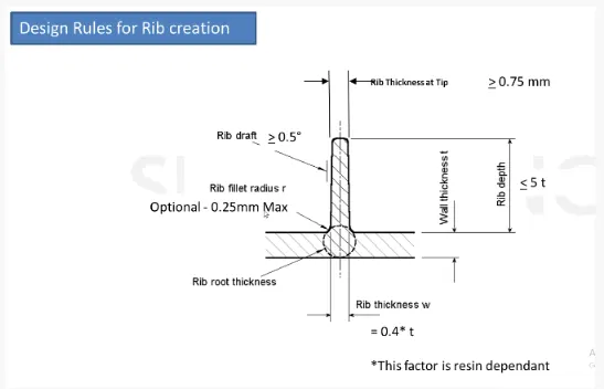
- Taller Ribs provide great support, Rib height might approximately taken as 5 times the base thickness.
- For wall thickness less than 1 mm, rib thickness is same as the wall thickness.
- A Draft of 0.5 degrees per side is the minimum limit.
- Rib thickess can be taken as 0.4 times the base thickness.
- Minimum thickness at the rib tip is 0.75 mm.
- Optimum rib fillet radius can be taken as 0.25 mm which is optional.
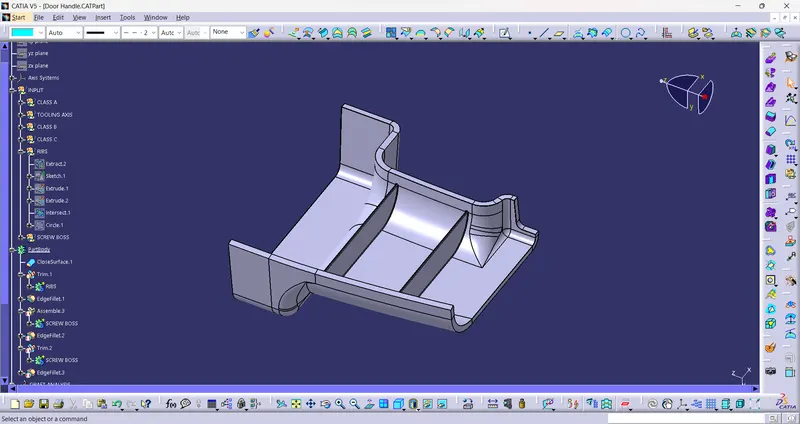
- Sketch Used For Rib Creation
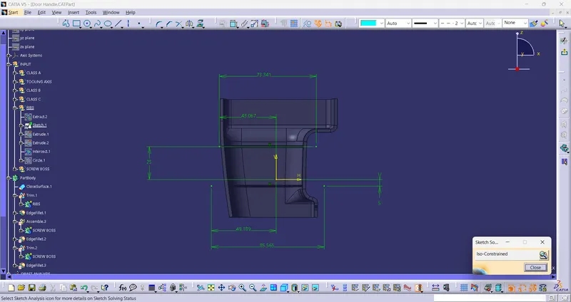
- RIB
SCREW BOSS DESIGN-
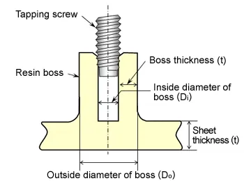
- Bosses are commonly used for attacchment and assembly of plastic components.
- They are used to aid in the assembly of molded parts by providing a channel for a screw.
- Bosses must not merge into side walls as they may lead to the formation of sinks.
- Open bosses can be used near a standing wall.
- Design Principle for Screw Boss Creation
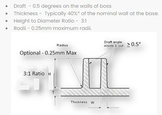
- The Boss thickness can be taken as 0.4 times the thickness of the component.
- A Draft of 0.5 degrees per side is the maximum limit.
- Height to Diameter ratio must be 3:1.
- Optimum fillet radius can be taken as 0.25 mm which is optional.
- Sketch Used For Screw Boss Creation
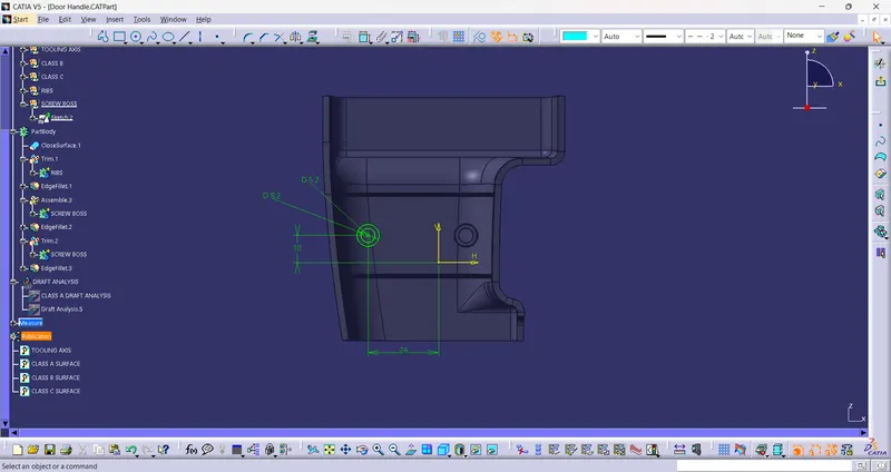
- SCREW BOSS
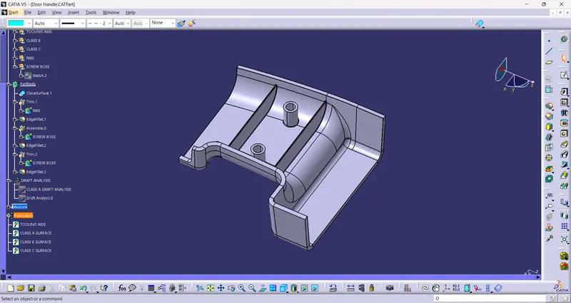
7. SOLID BODY DRAFT ANALYSIS
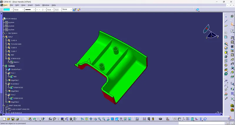
8. 3D MODEL
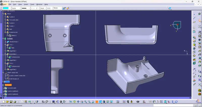
CONCLUSION:
- The Tooling axis and the Solid CAT part with B Side Features is created from the given Class A Surface and Draft Analysis is Performed.