Week 9 - Attachment Feature Creation (Ribs & Screw Boss) - Challenge 1
Aim: Create the rib and screw boss for the Drill Handle considering the design rules and perform the draft analysis for the final component.
Objective:
- Create the Tooling axis
- Design the class-B and class-C surfaces and join them.
- Use the Close Surface feature to make a solid body from the surface.
- Design the required Ribs and Screw Boss and analysis them.
- Perform the Draft analysis for the final component.
Tooling Axis :
Class-A surface is first analyzed to create the tooling axis. where the molds pull apart in injection molding. Tooling direction is essential for plastic product design as it decides the direction for mold separation.
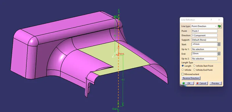
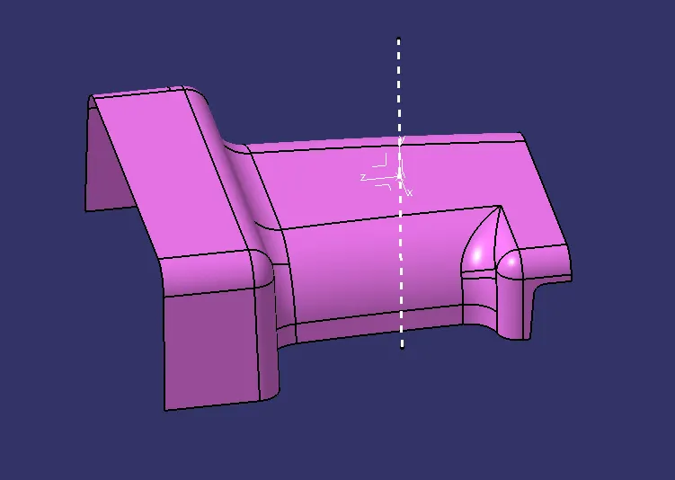
To create the tooling axis first we have to check the best suitable direction for tooling by using the compass. the y direction is suitable for creating the tooling axis because in the y direction most of the surfaces are clearing while performing draft analysis. Generally tooling axis is created using bisecting line method but here A line normal to the surface is created in the y direction and considered the tooling axis.
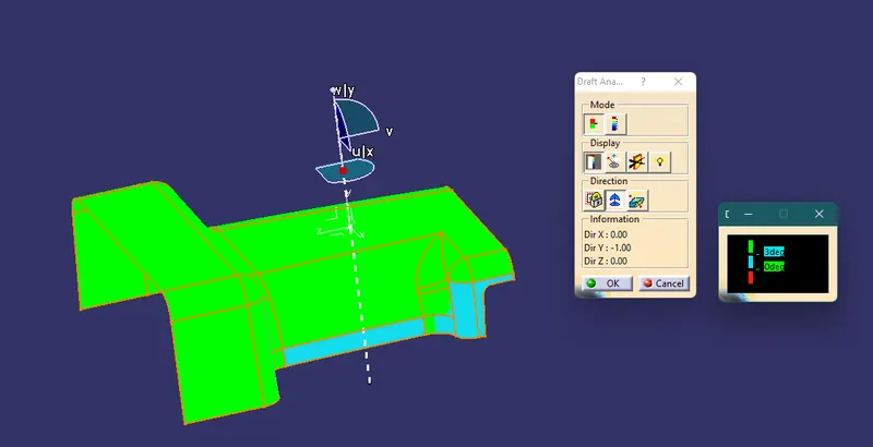
Draft analysis of Class- A surface
- The part created has to be changed to the material mode in the display frame.
- Compass is enabled and aligns it along with the tooling direction.
- The lock command is then applied to fix the compass along with the tooling axis.
- Color codes are classified and Draft angle is applied.
- Running point analysis is used to display permissible draft angles.
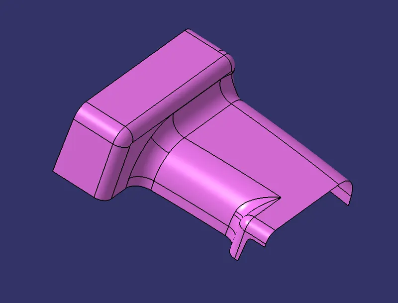
Given class A surface
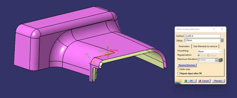
Creation of the class B surface the thickness of the component is 2.5mm
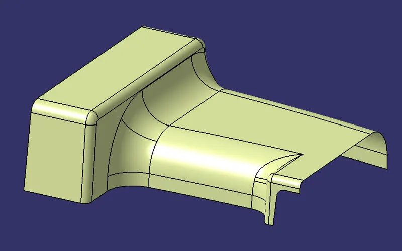
creation of class C surface
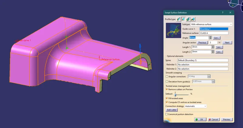
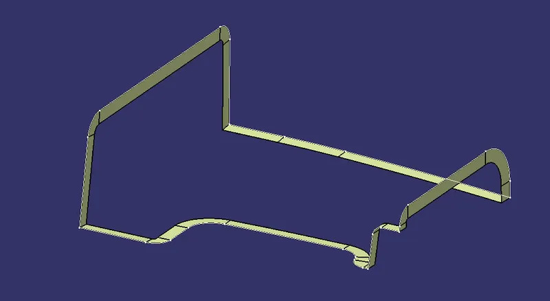
Joined class A and class C and trimmed with class B.
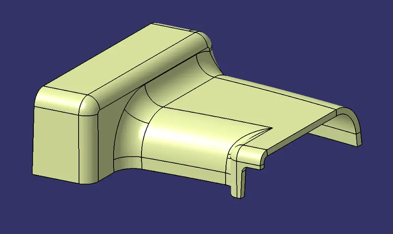
final plastic component Created by the close surface feature
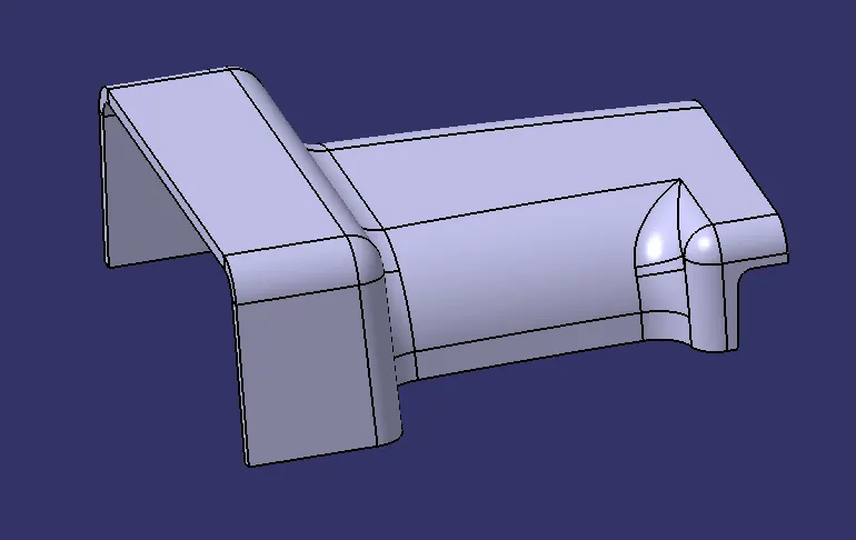
Attachment Feature Creation Ribs & Screw Boss:
Ribs:
Ribs are thin wall-like structures that add support and rigidity to injection molded parts. They are thinner than primary walls and are used to support these walls, as well as bosses, by running perpendicular to these structures. Ribs are often used to replace thick wall sections to avoid sink marks, warp, and voids.
The function of rib in plastic component:
Ribs are used to strengthen the walls of the mold without increasing wall thickness which means that minimize the problems that come into play when the wall thicknesses have to be increased. In essence, if the wall is too thick, warping and sinking can result so that the entire design may need to be rejected.
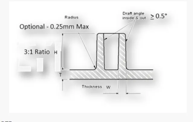
The analysis for the dimension is one of the very important analyses to avoid problems in the injection molding component. the problems like sink marks, flow lines, and weld lines. Then they create some standards for the creation of the ribs. That standard dimension is shown in the figure.
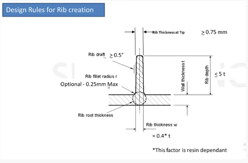
Draft angle- 0.5 degrees per side
Thickness – typically 30% to 40% wall thickness
Height<= 5 times wall thickness
Spacing 3:1 or 2:1 (steel height/ width ratio maximum)
Fillet radii: 0.25mm maximum.
Creation of ribs
Ribs sketch
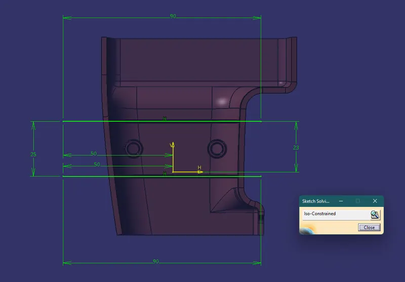
Next, the profile is padded, to find the height,h=Wall thickness * 5
=3*5
= 15 mm
Therefore, the height is 12.5 mm
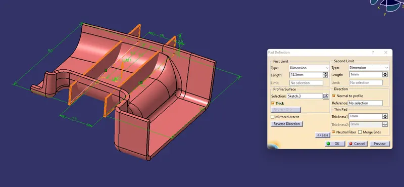
The padded surface is thickened,
Thickness,w=0.4*t
=0.4 *3
=1.2mm
Therefore, the thickness of the rib is 1.2 mm
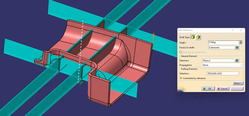
The draft is applied to the sides of the ribs. As per the design rule, the ideal draft angle is 0.5 deg.
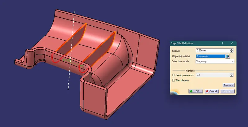
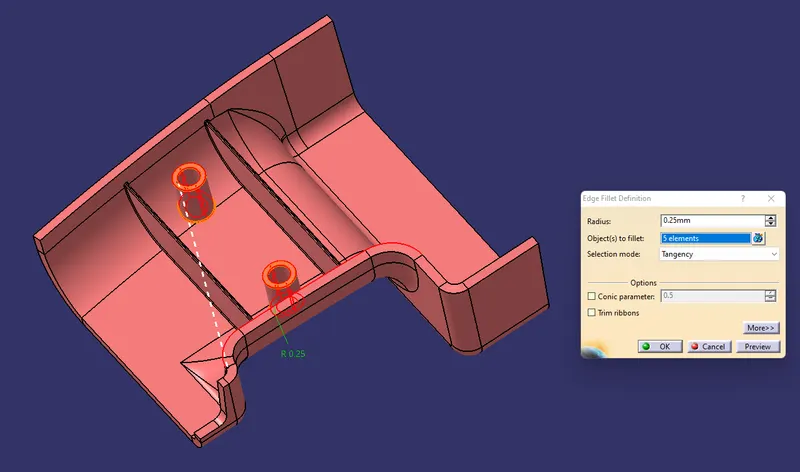
Fillet is applied to the faces of the rib with a fillet radius of 0.25 mm. Max 0.25mm (Fillet is optional).
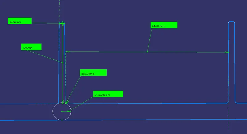
Now, we have to check for the Rib root thickness.
To check for the Rib root thickness, take an Intersection with the XY plane and the Drill handle component. Once we get to the intersection we have to create a tri-tangent circle at the rib area and measure it. The value must be within 30% greater of the wall thickness.
Screw Boss
Screw Boss features are commonly found in injection molding designs. They are used to aid in the assembly of molded parts by providing a channel for a screw.
Screw bosses are typically used to assist in assembly, as a receptacle for a screw or threaded insert, or as the locator for a mating pin on another part. Their primary use is to strengthen holes or slots in the surface present in the part model.
General Guidelines for Screw Bosses:
- Draft - 0.5 degrees on the walls of boss
- Thickness - Typically 40%* of the nominal wall at the base.
- Height to Diameter Ratio - 3:1
- Radii - 0.25mm maximum radii.
Sketch Used For Screw Boss
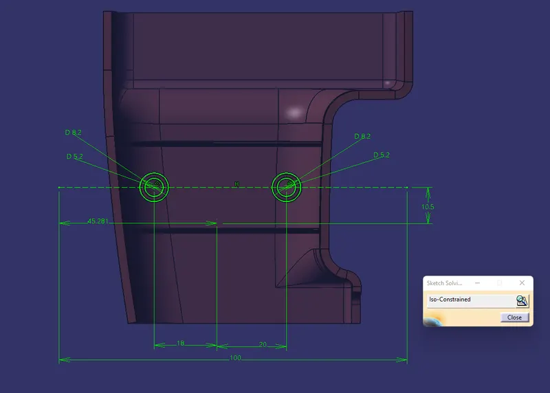
In this component design, the screw boss hole thickness is considered 5.2 M6 screw
For thickness, the design rule is as follows,
Thickness,w=0.6*T
T =3
=0.6*3
=1.8 mm
Therefore, the thickness of the boss is 1.5 mm per side.
for two sides
1.8 +1.8 =3.6mm.
5.2 + 3.6 = 8.8 is the ideal size for the screw boss.
using the pad feature we padded the sketch at the height of 12.5 The height to diameter ratio can be 3:1
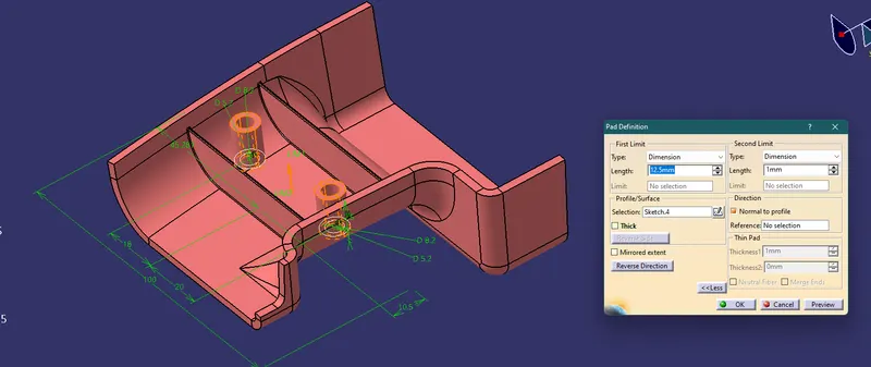
As per the design rule, the draft given for screw boss is 0.5 deg.
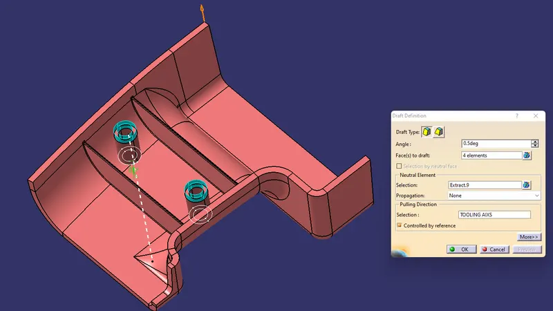
Then fillet is applied to the faces of the rib. As per the design rule, the fillet can be 0.25 mm