Week 9 - Attachment Feature Creation (Ribs & Screw Boss) - Challenge 1
The rib for the Door Handle
AIM:
Create the rib for the Door Handle considering the design rules.
OBJECTIVES:
CLASS-A SURFACE:
the class-A surface is used in the automotive design industry.it the describes the final production surface data for the aesthetic parts of the car.
CLASS-B SURFACE:
The Class B finish is a quality finish with only minimal imperfections.
CLASS-C SURFACE:
The interior surfaces not readily visible, surfaces that will be covered by another part when assembled, or surfaces which the Customer feels do not need to meet a high cosmetic finish.
DRAFTING ANALYSIS:
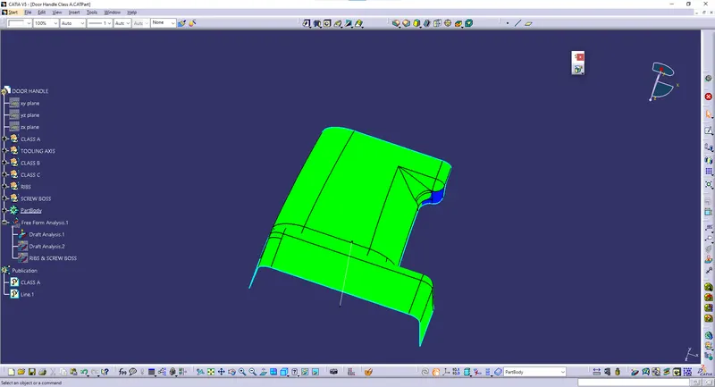
- Draft analysis is performed on the components where the ejection of materials happens after the material is made inside the tools.
- In the case of automotive sheet design manufacturing, the blank sheet after turning into automotive panels like Hood, Fender, Roof, Side Doors, Back Doors,bumpers need to be removed from Panel Dies.
- If a considerable amount of draft angle is not provided, the removal of components from the tool will be difficult.
- It’s the same in the case of mold(plastic component) after getting filled inside the core and cavity, it needs to get ejected easily with the help of ejectors.
Creating tooling axis:
- The ejection from the mold after manufacturing the interior trim must have the nominal 3-degree draft angle.
- hence the tooling directions created by considering the above factor and bisecting method is used.
- The base surface of the class-A was extracted to create a reference point on the surface using the point, create a line in the z-direction and an axis system was inserted to the point
- Tooling direction is the main consideration for plastic part and mould parts because it defines the movement of the mould part and the possibility of the plastic part coming out from the mould part (Core and Cavity).
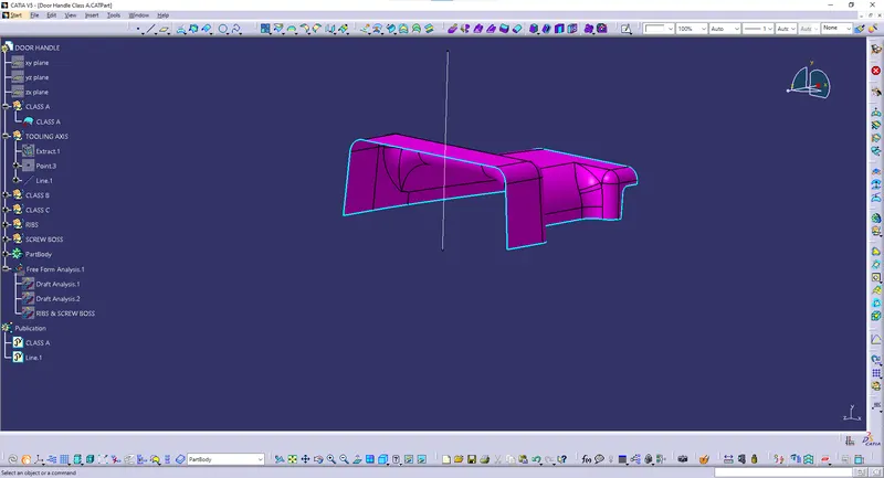
Class A surface:
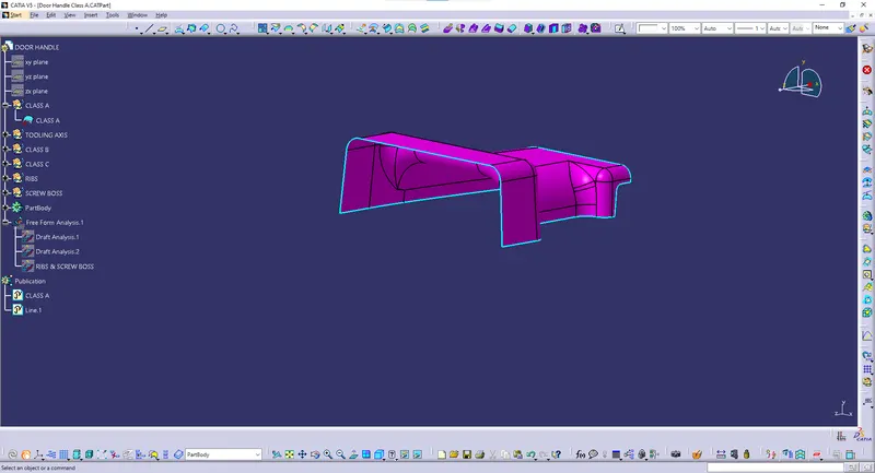
Class A Draft analysis:
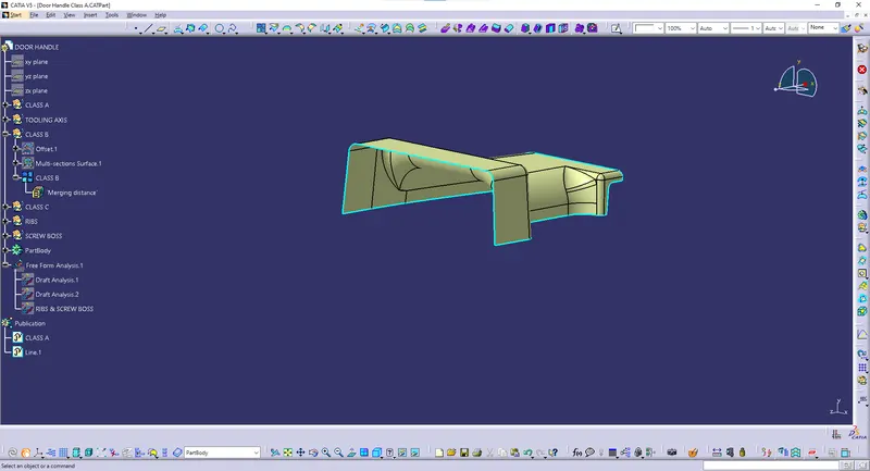
Creation of class B:
- Offset the class-A surface to 2.5 mm inward direction.
- Rework on the patches and discontinuity of the offset surfaces using the features like extract, multi-extract, sweep
- To ensure the continuity of the Class-B surfaces check the boundary command to find out the boundary.
- Hence class-B surface creation is done.
Creation of CLASS C SURFACE:
- Surface that joins class-A and class-B surfaces is class-C surface. Class C is often specified for interior surfaces not readily visible, surfaces that will be covered by another part when assembled
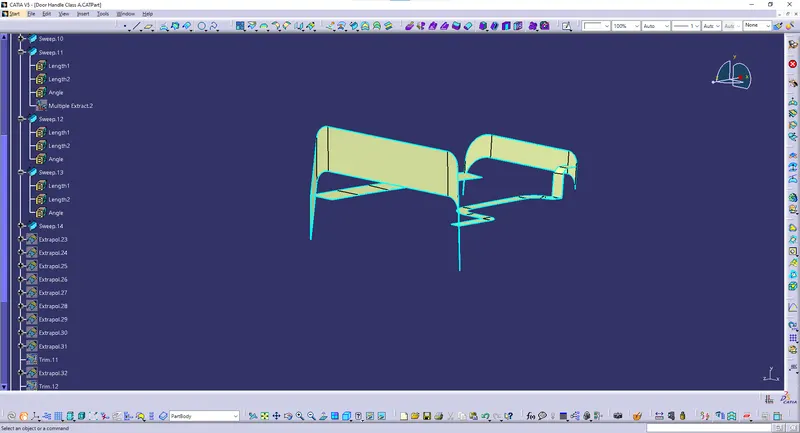
- Since it is a complex class-A surface, we cannot simply create the class-A boundary curve and sweep it at one shot.
- Hence, we need to create smaller curves using multi-extract command and then create sweep of 90 degree with reference to the surface option. sweeps at the midportion of the bumper should have a 90 degree value to pass the draft analysis.
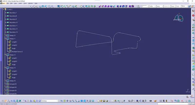
Class C boundary surface:
Class C sweep:
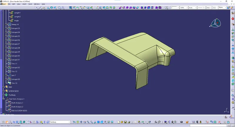
class A & B & C:
B SIDE FEATURES CREATION
RIB CREATION
- Design Principle for Rib Creation
-
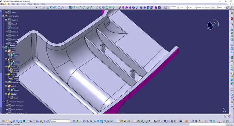
Ribs are thin wall protrusions that extend perpendicularly from a wall or plane. They are usually found in clusters offering support to a plane that would have otherwise been too thick, but can also be stand-alone support for a single wall. They are commonly used to provide additional support and strength to a part. Thickness and location are essential to rib design.
First, the base surface where the rib has to be created is extracted using the Extract command. A positioned sketch is created and the profile for the rib is drawn.
-
Next, the profile is extruded, to find the height,h=Wall thickness * 5
=2.5*5
= 12.5 mm
Therefore, the height is 12.5 mm
-
The extruded surface is thickened,
Thickness,w=0.4*t
=0.4 2.5
=1mm
Therefore, the thickness of the rib is 1 mm
SCREW BOSS DESIGN
- Design Principle for Screw Boss Creation
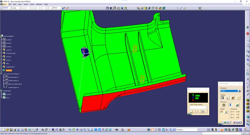
Draft analysis of Ribs & Screw bosses:
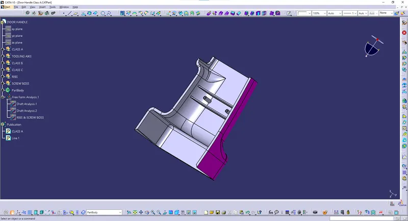
Solid body:
Conlusion:
Creation of the rib for the Door Handle and the Screw boss for the Door Handle is completed.