Week 8 - Challenge 1 - Base Bracket Design
BASE BRACKET DESIGN
AIM: To create a Base Bracket Component through a given Class A Surface and perform tooling axis for the given class A surface and show the draft angle and draft analysis.
PROCEDURE:
- To setup the class-A surface and to creating a tooling axis
- add draft angle
- To create a base surface of model
- To create a B-surface
- To create a C-surface and surface model of a base bracket
- Publish the all class surfaces
MATERIAL USED IN BASE BRACKET:
ABS or Acrylonitrile butadiene styrene is a common thermoplastic polymer typically used for injection molding applications. This engineering plastic is popular due to its low production cost and the ease with which the material is machined by plastic manufacturer,its natural benefits of affordability and machinability.
- Impact Resistance
- Structural Strength and Stiffness
- Chemical Resistance
- Excellent High and Low Temperature Performance
- Great Electrical Insulation Properties
- Easy to Paint and Glue
TOOLING AXIS:
The Tooling Direction is basically the direction that the mold pulls apart. The mold is built in two separate pieces, basically. You have a Cavity side and you have the Core side. The Core pulls apart from the Cavity and that's the Dyeline or the Tooling Direction.
MATERIAL USED IN BASE BRACKET:
ABS or Acrylonitrile butadiene styrene is a common thermoplastic polymer typically used for injection molding applications. This engineering plastic is popular due to its low production cost and the ease with which the material is machined by plastic manufacturers, its natural benefits of affordability and machinability,
- Impact Resistance
- Structural Strength and Stiffness
- Chemical Resistance
- Excellent High and Low Temperature Performance
- Great Electrical Insulation Properties
- Easy to Paint and Glue
CLASS-A:
- In automotive design application Class A surfaces are created on all visible exterior surfaces (ex; body panels, bumper, grill, lights etc.) and all visible surfaces of see-touch in interior (ex: Dashboard, seats, door pads etc.)
- class A surface should be given and we dont make any dimension changes.
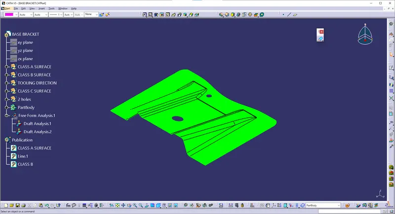
DRAFT ANALYSIS:
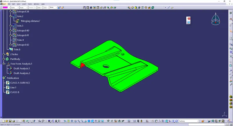
Draft analysis is performed based on color ranges identifying zones on the analyzed element where the deviation from the draft direction at any point, corresponds to specified values. Minimum draft angle is considered as 3 degree.
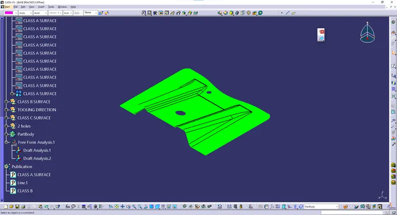
CLASS-B:
- To create the class B surface,we want extract and untrim the class-A
- After extract and untrim the selected part can be offset and trim the unwanted element
EXTRACT-CLASS B:
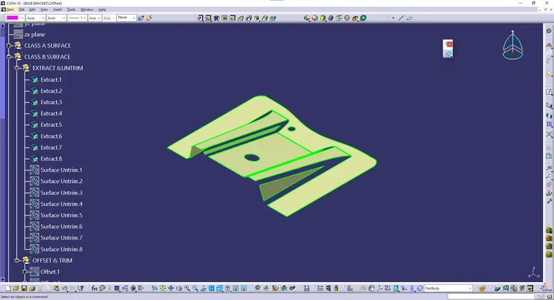
SURFACE AND UNTRIM:
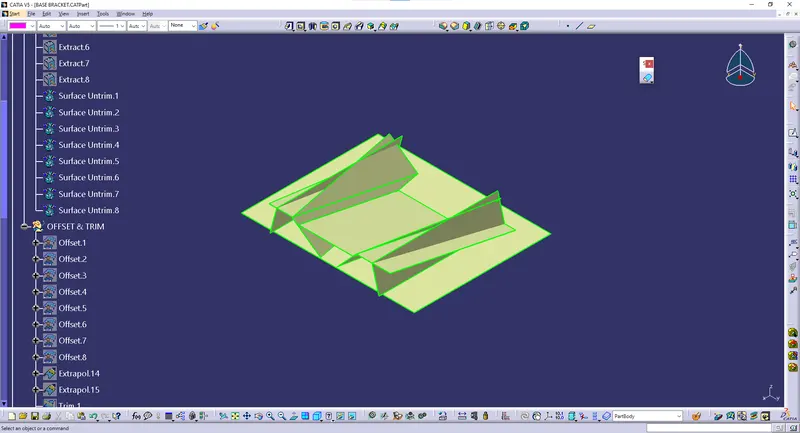
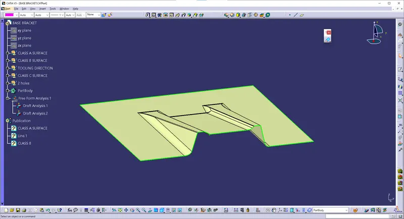
Class C Surface:
It is the combination of Class A, Class B and Class C surfaces. To create a class C surface, I used the sweep command by considering the outer boundary of the class A surface. In the sweep command. Now select the outer boundary and tooling axis, give 2.9 deg in the angle (the draft angle for a plastic component is 0.5 to 3 deg) and select the direction to sweep, in this condition the class B surface is under the class A surface so select the inside down arrow to sweep. The same procedure is repeated for the two circles on the class A surface. Now I joined all the sweeped surfaces by using the 'join' command and then I trimmed the Class A, Class B and Class C surfaces to make a closed surface, to make a Solid body.
- SWEEP
- BOUNDARY
- SMOOTH CURVE
- MULTIEXTRACT
- TRIM
CLASS C BOUNDARY:
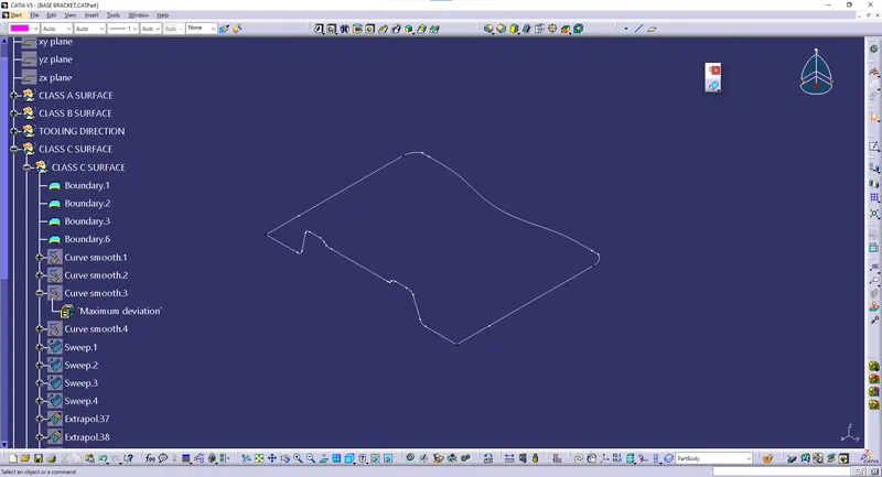
SMOOTH CURVES CLASS C:
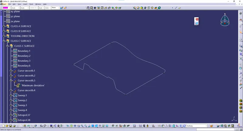
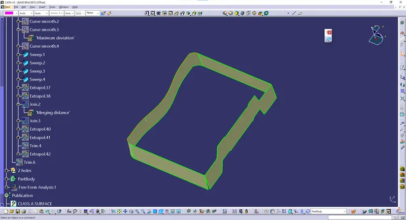
DRAFT ANALYSIS C:
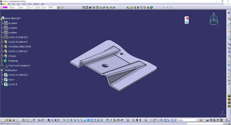
FINAL PART:
CONCLUSION:
Hence the base bracket part,by using draft analysis is finally converted into solid part.