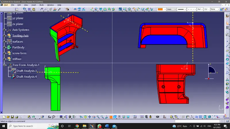
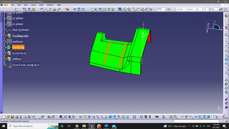
Week 9 - Attachment Feature Creation (Ribs & Screw Boss) - Challenge 1
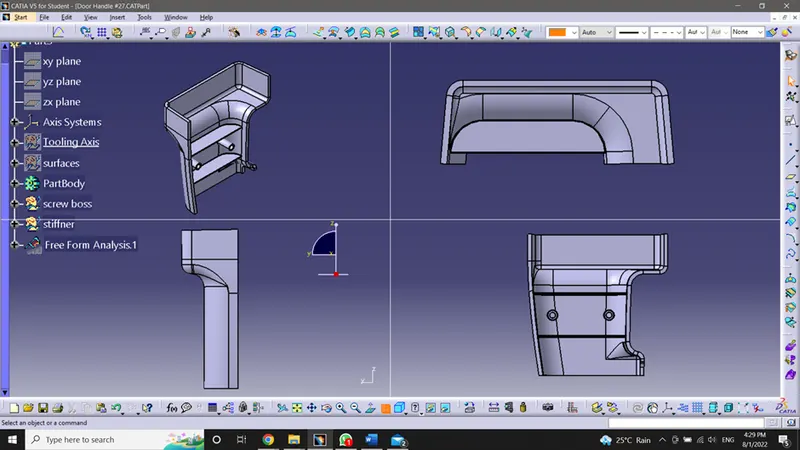
Screenshots of Completed Design
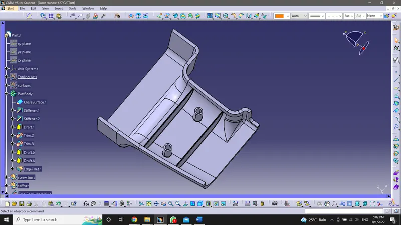
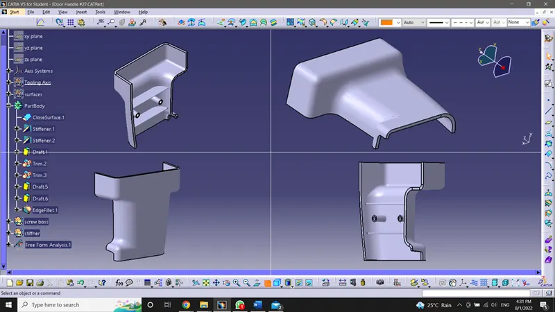
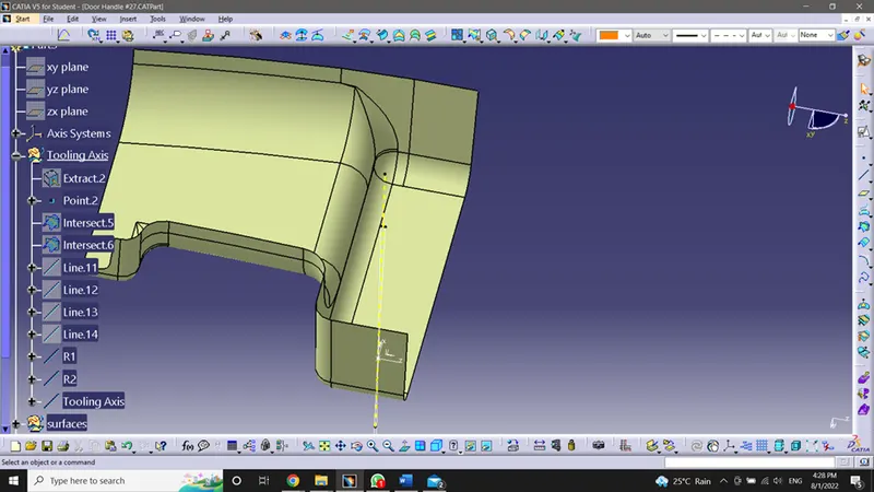
Tooling Axis
- A point is marked on the extracted surface of the Class-A, and an axis system is inserted on that point.
- made intersects with respect to respective planes on the new axis system.
- And four lines are created using point-point line type on the profiles on the two planes.
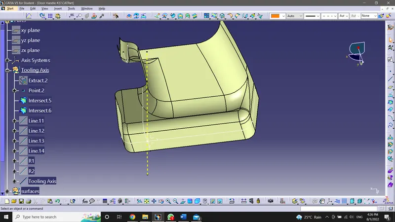
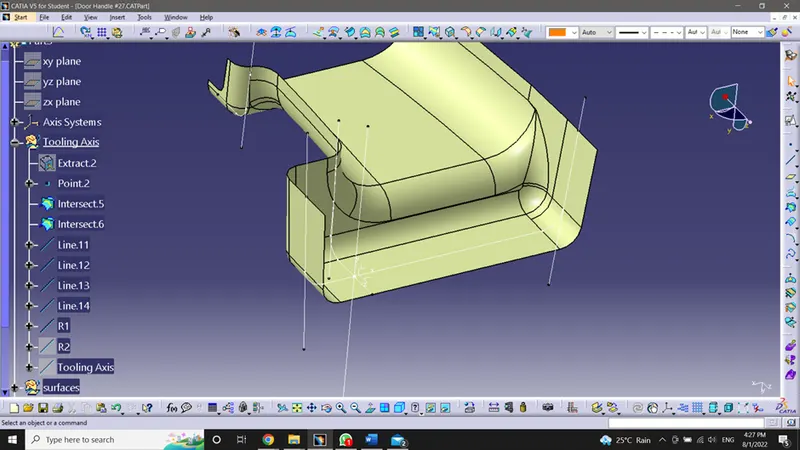
- Two lines 'R1' and 'R2' are created on the origin point by bisect line type using respective lines reference to the planes.
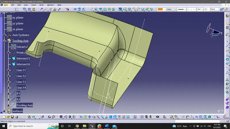
- Using the R1 and R2 creates our Tooling axis by bisect line type through the origin point of the new axis system.
Drafting Analysis of Class-A Surface
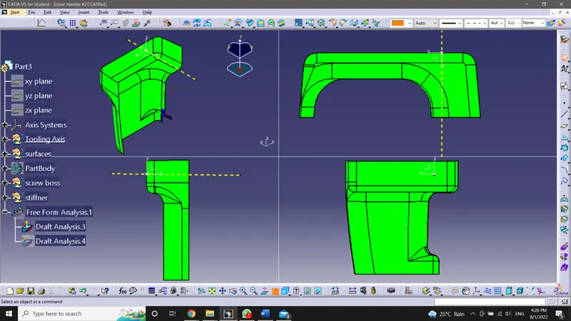
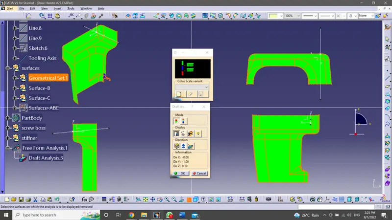
Drafting analysis of Solid body