Week 9 - Attachment Feature Creation (Ribs & Screw Boss) - Challenge 1
REPORT :
Creation of Tooling Axis :
1. First insert a point on the surface of the class A by extracting the base
2. The selected surface is in such a way that the majority portion of the object have to be cleared and the remaining portion is in such a way that it can be cleared in the tooling direction.
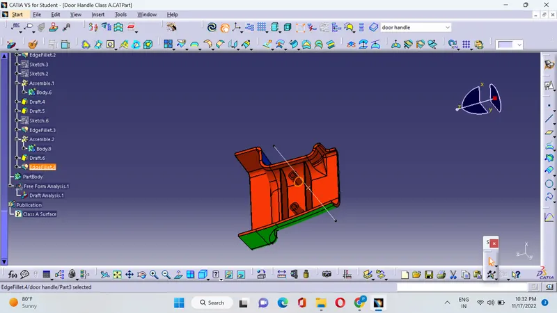
Draft Analysis :
1.Green color indicates that the degree is from 0 to 3 degrees
2.Red color indicates that the degree is from 0 Degrees
3.Blue color indicates that the degree is from 0 to negative
Class A :The surface is defined has the object that we can see with our eyes and it is said to be the aesthetic surface,this surface should be smooth and free from defects and the surface should be smooth.
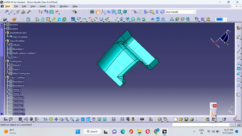
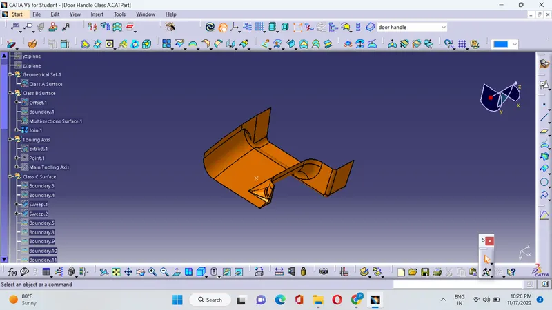
Class B : This surface is defined has the surface parallel to the class A or it is said to be the engineering surface where all the engineering features takes place.
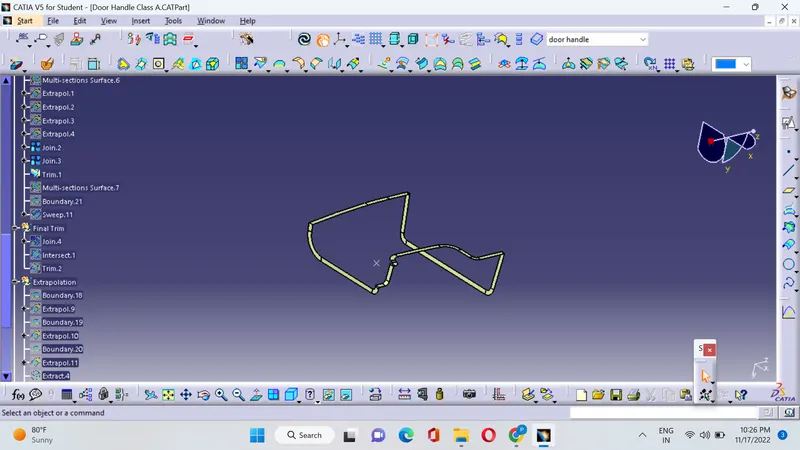
Class C : This surface is defined has the surface that joins both the class A and C .
Procedure :
1.Offset the class A surface for 2.5mm .This surface is the engineering surface the check for the patches if any
2.The patches are to be closed with the commads like join,multiple extract and extrapolate.
3.And trim the extrapolated surface on all the sides of the patches measure the fillet side and perform fillet operation of necessary.
4.The Class C surface is generated by using the sweep command.
5.Join all the final surfaces of the class A,Class B and Class C and ensure proper geometrical set.
6.After joining the surface close the surface by using the command close surface in part design.
7.Then perform the draft analysis on the closed surface.
Draft analysis is shown in the below figure :
How to Create Ribs :
1.Follow all the design standards as mentioned in the video after the creation of the solid object,take a point on the surface of the object and create a plane.
2.Now draw a plane line on the surface and extrude it of height 12.5(Taken has 5*thickness at the base).
3.Now pad the line and thicken it for 1 mm The thickness it taken has(0.4*thicknees at the base 2.5mm)
4.Now draft the pad on both the sides by selecting the plane as the neutral element and pulling direction has tooling axis.
5.After drafting Union trim the body with the main body and remove the extended surfaces that are outside the surfaces.
6.Now create the same rib by taking some distance from this rib.
Creating Screw Boss :
1.Let us take a M5 screw the inner hole should be of dia 5.2 mm and the outer boss of diameter (5.2+1.5*2) has 8mm
2.Create a sketch of these diameter and pad it.
3.Later repeate the same procedure has done for the ribs.The difference is that the draft should be done on both outer circle and the inner circle.
Conclusion :
The result is obtained by taking the design standards and a Screeboss of m5 size is produced on the door handle.