Week 9 - Attachment Feature Creation (Ribs & Screw Boss) - Challenge 1
Requirement:-
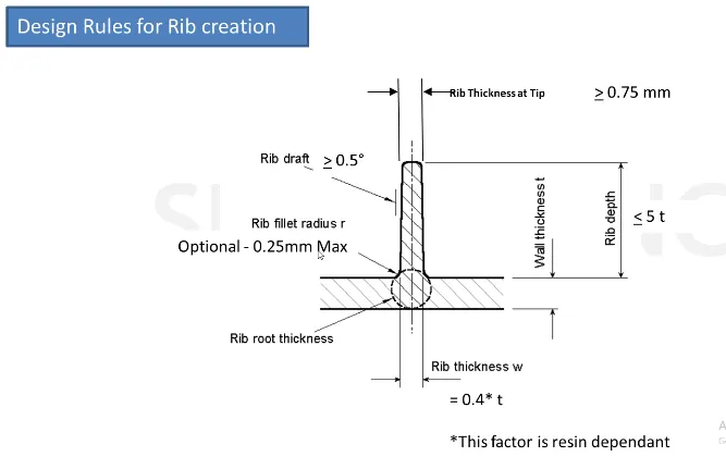
Create the rib for the Drill Handle considering the design rules mentioned in the video.
Create the Screw boss for the Drill Handle considering the design rules mentioned in the video.
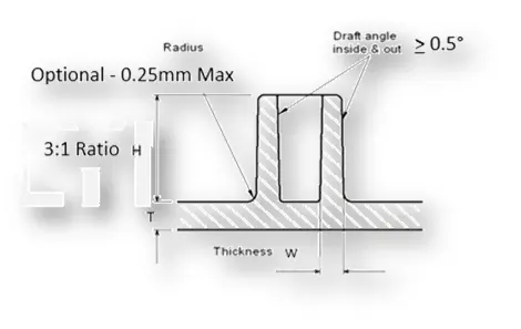
General Guidelines for Bosses:
- Draft - 0.5 degrees on the walls of boss
- Thickness - Typically 40%* of the nominal wall at the base.
- Height to Diameter Ratio - 3:1
- Radii - 0.25mm maximum radii.
Checkpoints
1) To check the continuity of Class A surface
2) Find the tooling Axis of the component
3) Making B surface
4) making C surface
5) combining surfaces and creating closed body
6) working on creating Ribs and Screw Boss
Definitions:-
Class A surface:- Class A surfaces are those aesthetic/free-form surfaces, which are visible to us (interior/exterior), and have an optimal aesthetic shape and high surface quality.
Tooling Axis:- The direction in which the mold or core and cavity opens is the tooling axis.
Creating Tooling axis:- Using the tooling axis created along the x and y-axis, these tooling axes are used for the creation of the tooling axis by a bisecting method where the two lines and point will be selected as inputs.We check the best possible tooling direction (X,Y,Z ) and find where all faces can be represented using tooling Axis
After choosing the particular direction we create Intersection points on the remaining axis were we get mean point to create the tooling axis.
This intersection can be done by Axis system or thru creating a plane.
Then we create line reflecting the surface which are difficult to visulize for the direction (parallel to axis faces ) . As parallel surface might get not clear but perpendicular face get cleared as they reflect on the surface direction.
Now we create a Bisecting Line with two line and point to get the output line (Tooling Axis).
Steps to work
Initially inorder to create Rib's and Screw we created a closed Solid Body by creating tooling Axis and using A surface and then creating B and C surfaces and all surfaces are represented Below!
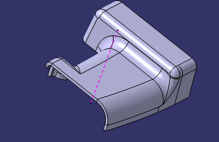
Initial Class A surface Draft analysis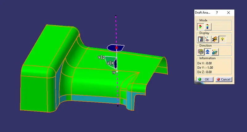
Final surface after Combinationb of A+C surfaces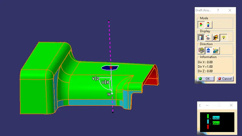
Tooling Axis
Here all begin with Tooling axis creation which is done by extracting surface and creating a line normal to surface.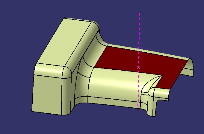
B surface 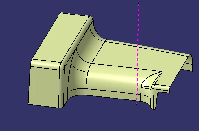
B offseting the a suurface upto required thickness and then working on areas where the surface couldn't be extracted
Connecting surface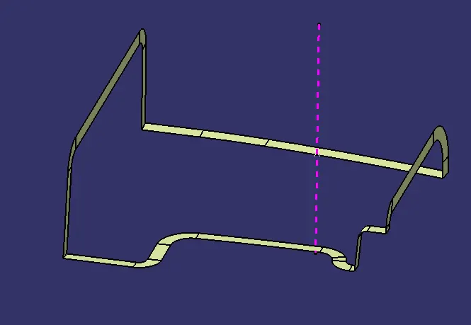
By combing B+C surface and final surface is connected with extracted A surface to get closed surface 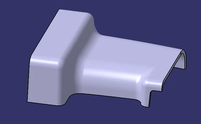
Final solid body
________________________________________________________
Designing RIB's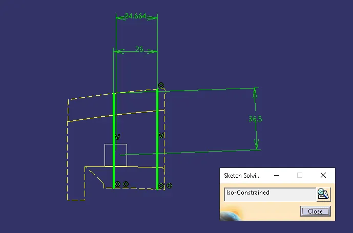
Considering a Plane and creating as sketch by maintaining the Design rules following the above mentioned criteria
Now Extracting the surfaces and then thicken them neutrally 0.4*t(2.5) = 1 mm
no drafting the surface and then filleting as per the measurements mentioned.
Finally creating anew part bodya nd adding to main body!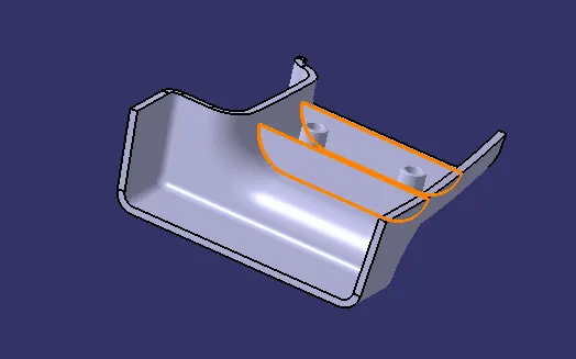
Creating Screw Boss
Similarly like Ribs we use plane and create sketch for screw Boss as per the measurement mentioned
then the pad operation is done and then following the drafting and filleting the surfaces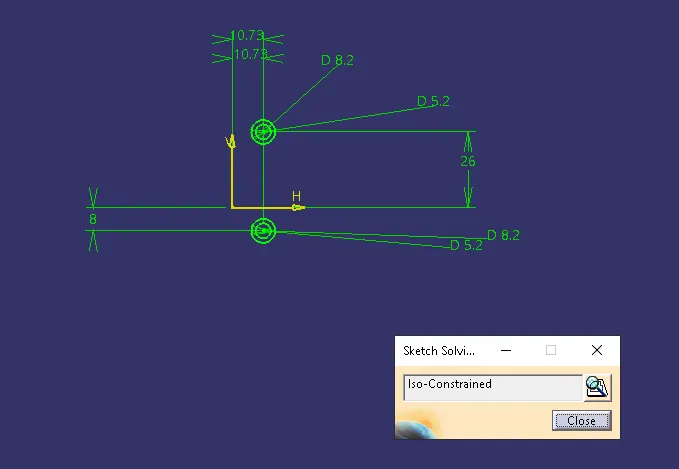
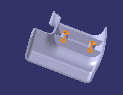
The checkpoints for above while creating is checking
Draft
Thickness
Height to diameter ratio
radii
checking the direction cosidering the type of ejection!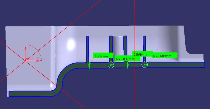
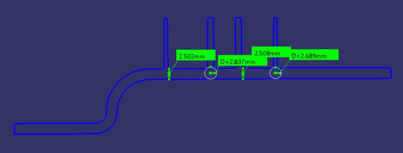
Section view checking the points worked or not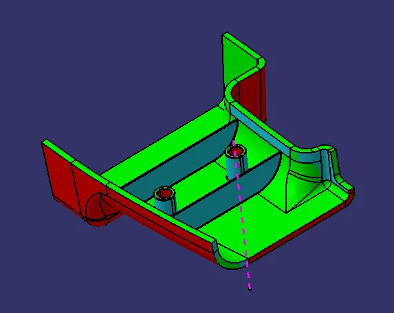
Isometric view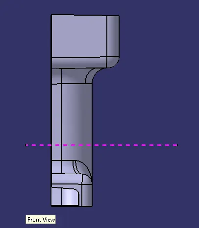
Front View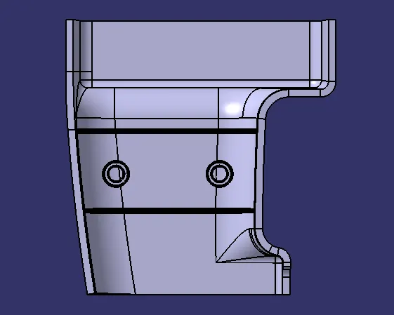
Left view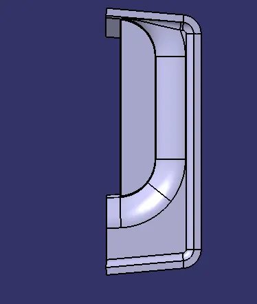
Top view
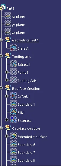
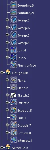
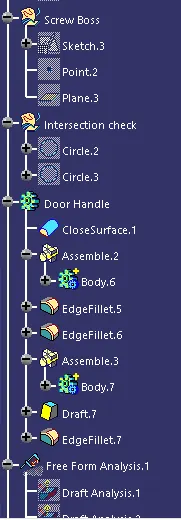
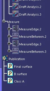
Tree Structure