Week 8 - Challenge 6 - Core & Cavity Design
Requirement :-
Create the Core and cavity blocks for the switch bezel designed in the earlier challenge.
NOTE:
- Tree Structure
- Tooling Axis
- Switch Bezel Solid / Surface body
- Parting Line and Parting Surface
- Ensure Proper Tree Structure
- Geometrical sets should have a proper name based on the sketches present inside of it
- All the sketches should be created under the Geometrical set
- Use the Close Surface feature to make a solid body from the surface.
- Publications: Use the publication option and publish the below
- Report
- A detailed report should be done explaining the draft analysis and the tooling axis creation. An explanation should be given on the way of creating the tooling axis, particularly the Bisecting method.
Definitions:-
Tooling Axis:- The direction in which the mold or core and cavity opens is the tooling axis.
Tooling Axis creation:
Using the tooling axis created along the x and y-axis, these tooling axes are used for the creation of the tooling axis by a bisecting method where the two lines and point will be selected as inputs.
We check the best possible tooling direction (X,Y,Z ) and find where all faces can be represented using tooling Axis
After choosing the particular direction we create Intersection points on the remaining axis were we get mean point to create the tooling axis.
This intersection can be done by Axis system or thru creating a plane.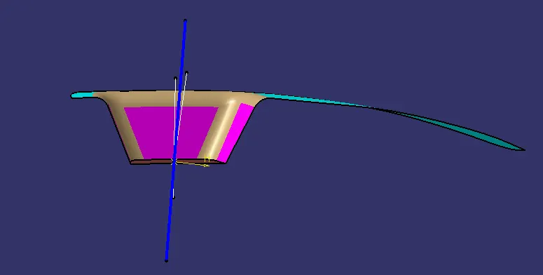
we create a Bisecting Line with two line and point to get the output line (Tooling Axis).
Design procedure:
There are 4 major elements considered in core and cavity design. they are Core, Cavity, Parting Surface and parting line.
Core and cavity are the two halves of complete mould in which either of them is fixed and other one is movable. During injection moulding, core and cavity is pressed against each other tightly to create hollow space and avoid leaking of material. The surface where the two halves are joined is called parting surface. The outline of the component at the parting surface is called parting line.
Below are the images related to above mentioned points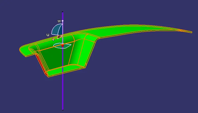
Here we can see in the draft analysis, component is observed for parting line. The surfaces having positive draft will be cleared in core side. In switch bezel, parting line is observed at B surface side.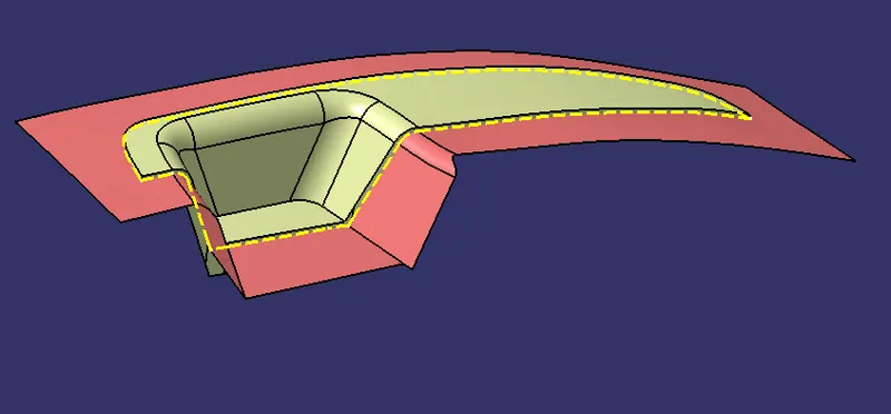
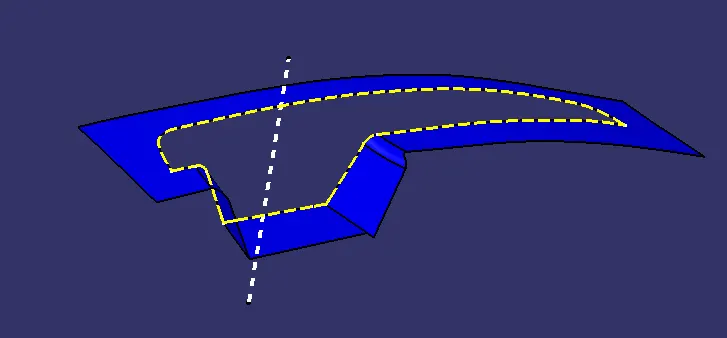
For Core design, class A surface trimmed with class C surface is taken. The required trim is taken from component design constructions.
Then it is trimmed with B surface considering outside of B surface as parting area.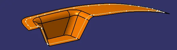
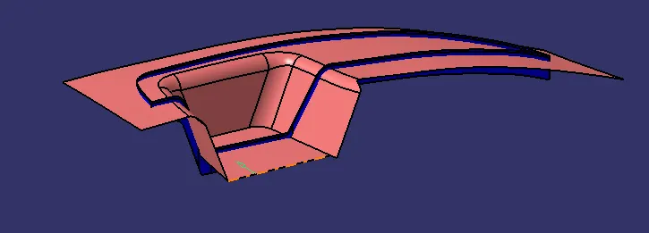
A sketch of rectangle is drawn in top view and it is extruded along the tooling direction checking the boundaries are with in the component!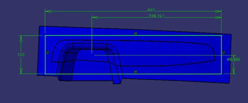
After extruding the surface! These two surfaces are then trimmed to get core shape. Top of the extrude is closed using fill surface operation to get the closed volume.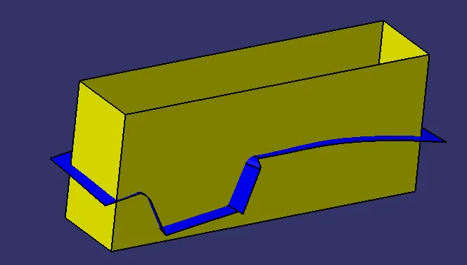
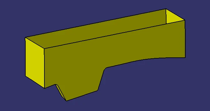
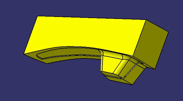
This closed volume is then converted into solid body.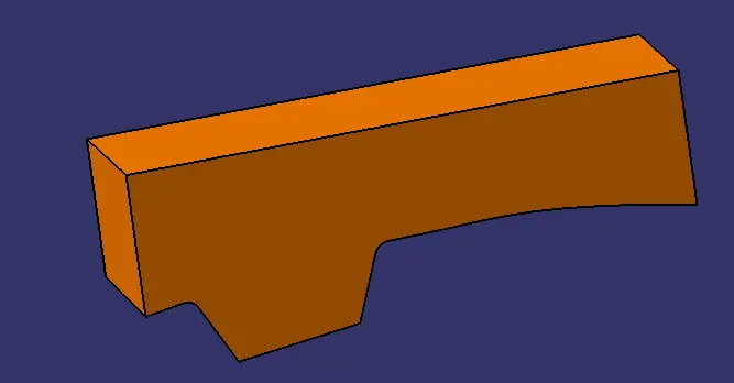
Similarly, For Cavity design, B surface is trimmed with the rectangular extrude. The bottom open part is closed to get closed volume. This closed volume is then converted in solid body.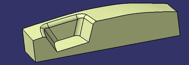
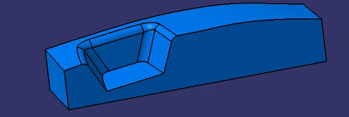
Using intersect we view the section of complete Mould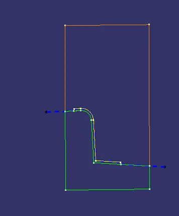
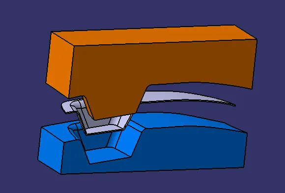
Using translate gave the gap to view the area between core cavity and mould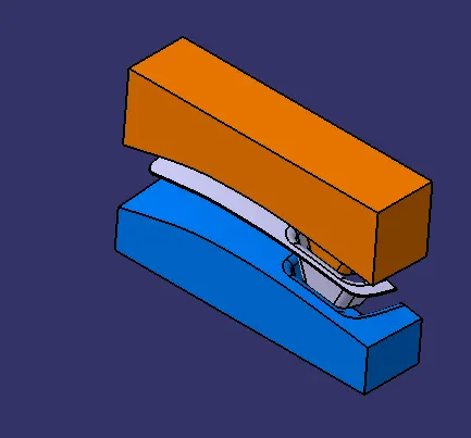
ISOmetric View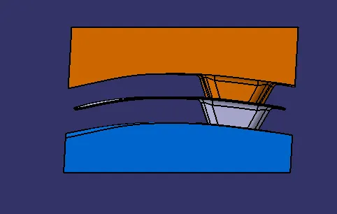
Front View
Side view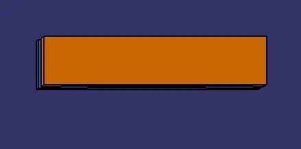
Top View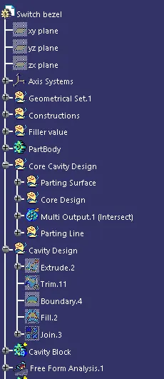
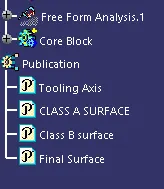
Tree Structure