Week 8 - Challenge 4 - Bumper
Requirement:-
Create the Bumper Plastic component through the given Class-A surface. To begin with, the tooling axis for the given Class-A Surface should be created meeting the requirements of the draft angle and at the end perform the Draft analysis on the model.
Take the Thickness of the component to be 3 mm
Checkpoints
1) To check the continuity of Class A surface
2) Find the tooling Axis of the component
3) Making B surface
4) making C surface
5) combining surfaces and creating closed body
Definitions:-
Class A surface:- Class A surfaces are those aesthetic/free-form surfaces, which are visible to us (interior/exterior), and have an optimal aesthetic shape and high surface quality.
Tooling Axis:- The direction in which the mold or core and cavity opens is the tooling axis.
Steps to work
STEP1
Initially check the connectivity of the surface, this can be done by creating boundaries or by simply using the join option such that any openings can be easily visualized.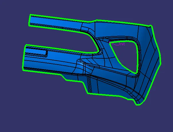
Tooling Axis creation:
Using the tooling axis created along the x and y-axis, these tooling axes are used for the creation of the tooling axis by a bisecting method where the two lines and point will be selected as inputs.
We check the best possible tooling direction (X,Y,Z ) and find where all faces can be represented using tooling Axis
After choosing the particular direction we create Intersection points on the remaining axis were we get mean point to create the tooling axis.
This intersection can be done by Axis system or thru creating a plane.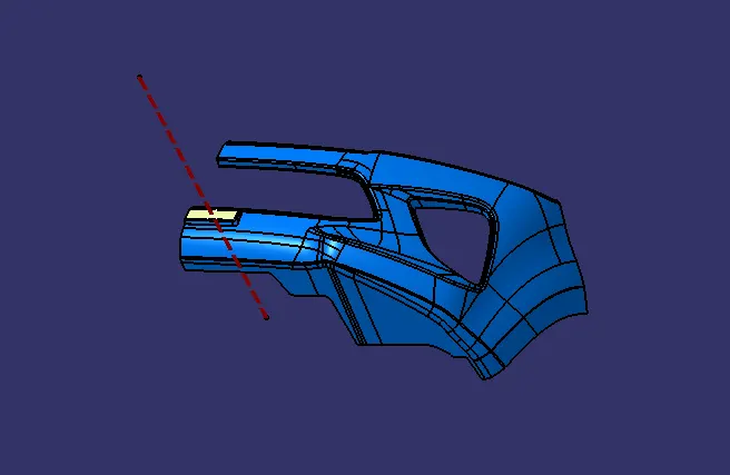
Here we extracted surface and centered the point and took tooling axis as line normal to the surface!
STEP 2
Draft Analysis:
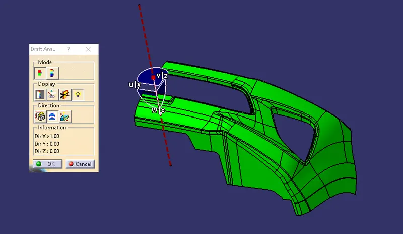
Draft analysis is done after determining the tooling axis, draft analysis is used to check whether the minimum draft (3 degrees) is maintained or not.
Compass is used to define the draft direction.
If the minimum draft 3 degree is provided the whole component changes in to green colour
STEP 3
B Surface
Now for creating the B Surface Here by offect the entire a surface with 3 mm there are missing surfaces (can be seen thru boundaries in image ) where to worked upon further.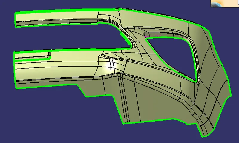
Final B surface creation!
Final B surface
Upon working with mutiple feature options created the entire B surface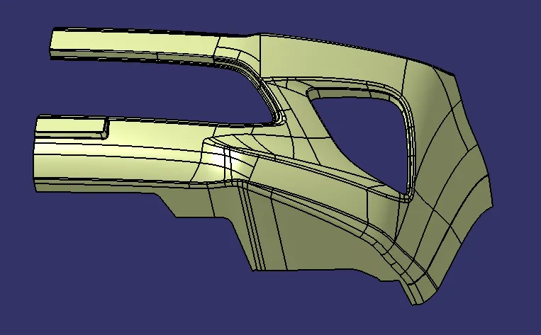
C surface
For making C surface initially we used the Boundary on the Class A surface
After Swept along downside as follows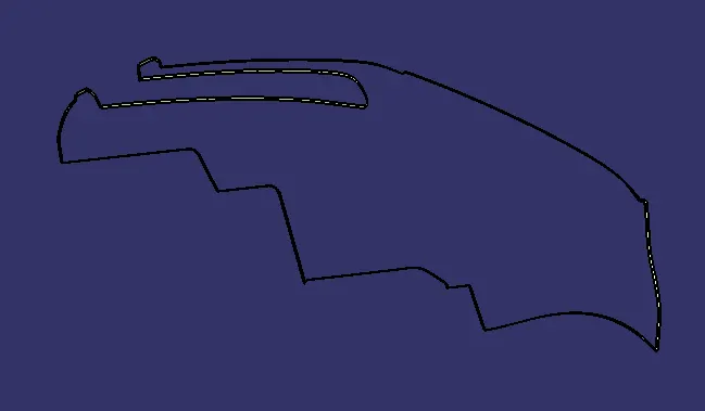
Now Using trim tool we combined B and C surface to get the final Closed Body 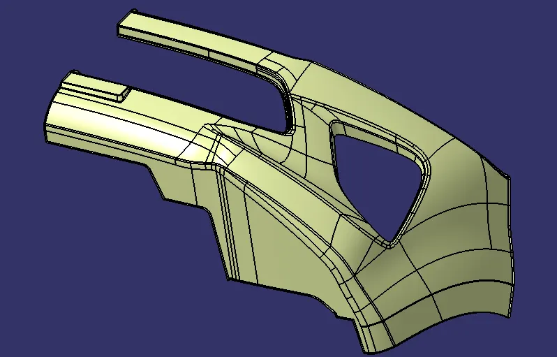
After Trim
Now using the Closed Surface command in part design created a solid Body !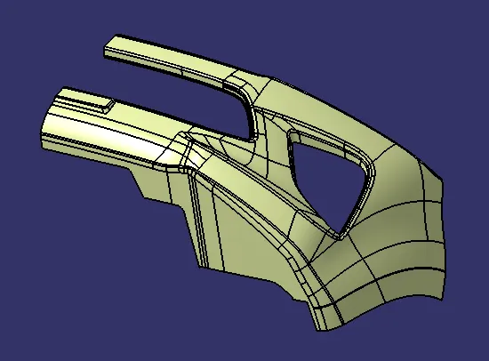
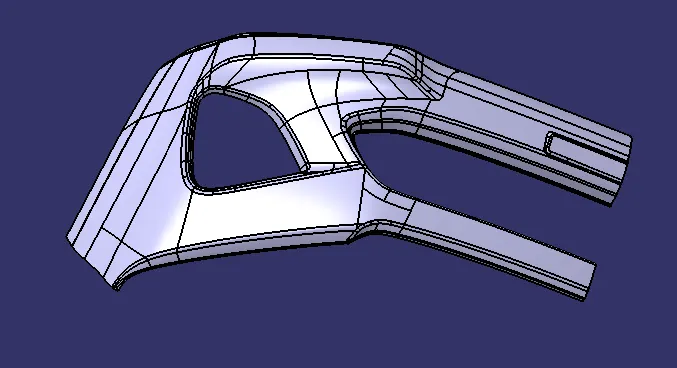
DRAFT ANALYSIS OF FINAL PLASTIC COMPONENT:
Following the similar steps performed for draft analysis of class-A surface, we obtained the following result
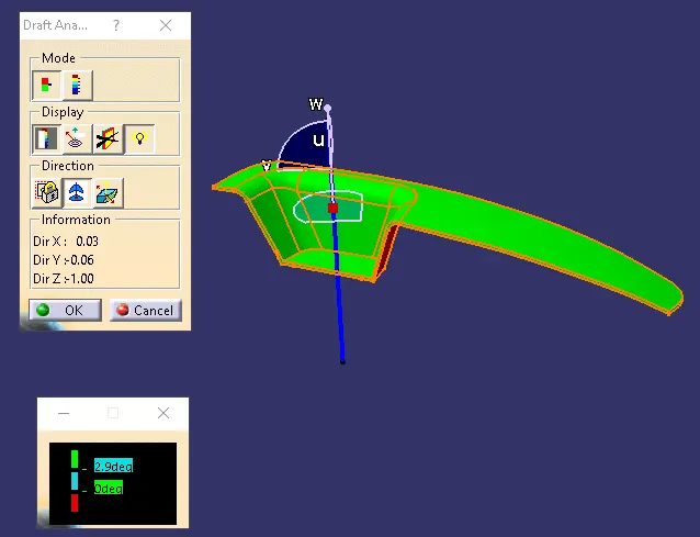
The draft analysis command enables you to detect if the part you drafted will be easily removed. This type of analysis is performed based on color ranges identifying zones on the analyzed element where the deviation from the draft direction at any point, corresponds to specified values.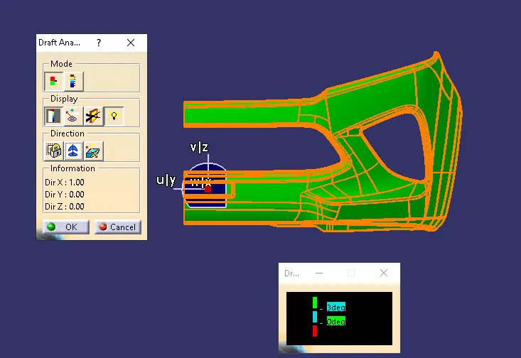
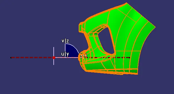
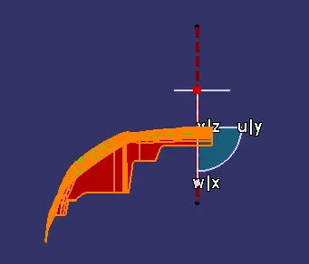
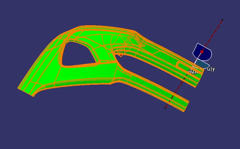
The above draft analysis in certain views
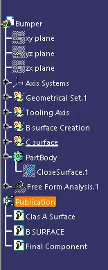
Tree Structure