Week 9 - Attachment Feature Creation (Ribs & Screw Boss) - Challenge 1
Draft analysis on Class A surface of DOOR HANDLE A
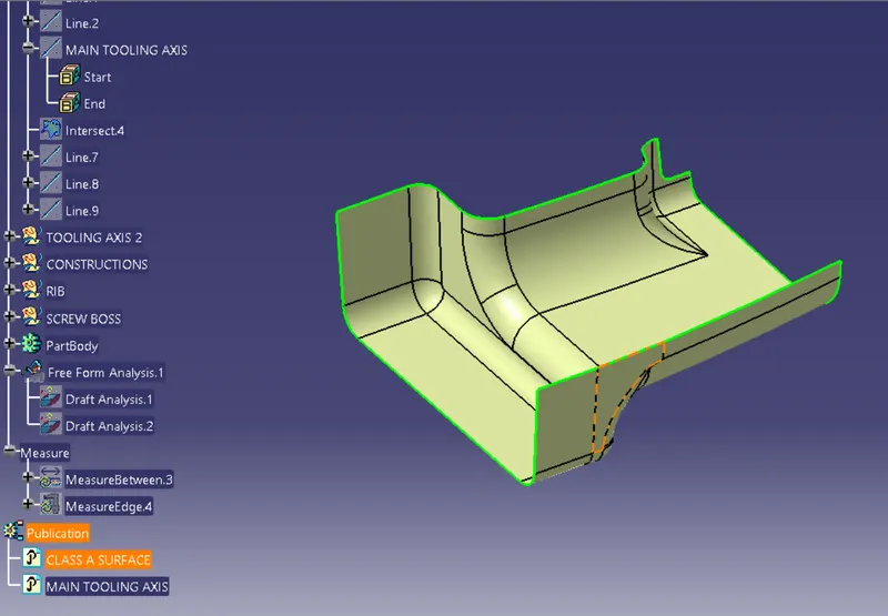
Open the draft analysis and move the compass to coincide with the Tooling axis as below.
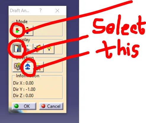
Lock the compass and check the radius/angles using the running analysis option
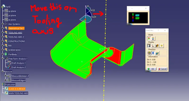
Set the color code for the draft angle i.e., green for above 3 degrees, Red for 0-3 degrees, and Blue for angle value lesser than 0.
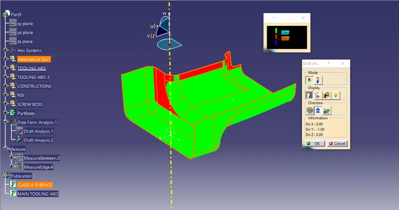
Click on the surface using the light effect, if the color goes green throughout means your draft analysis is good and ready for manufacture
Now creating the tooling axis by using an intersection and a dummy axis
open the file which contains the Class A surface, after creating a geometrical set "Tooling Axis" then select the most appropriate position, and in this select a base of the top flat surface.
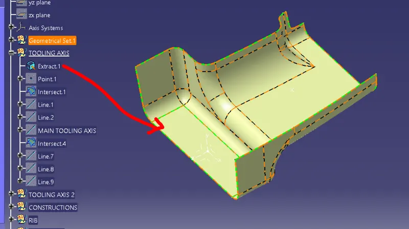
Then create a point at the surface extracted
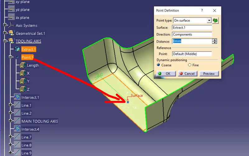
After that create a plane on the point created with reference to the Z direction/ZX Plane.
Then select the intersect tool that gives the intersection on the Class A surface.
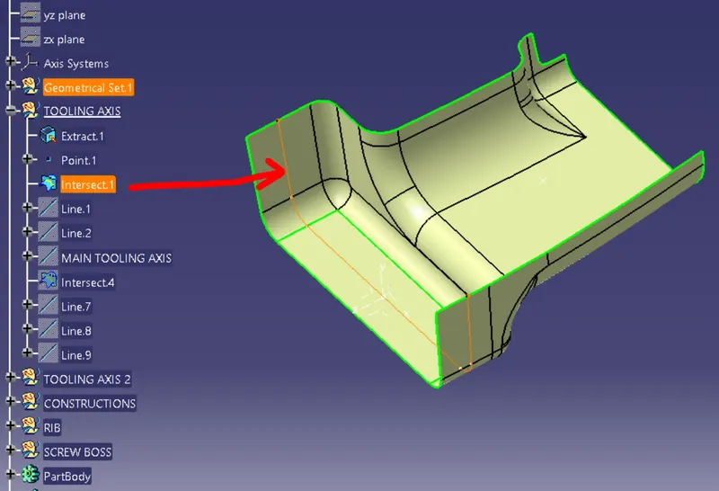
In this draw 2 lines using the point-point method below the screenshot.
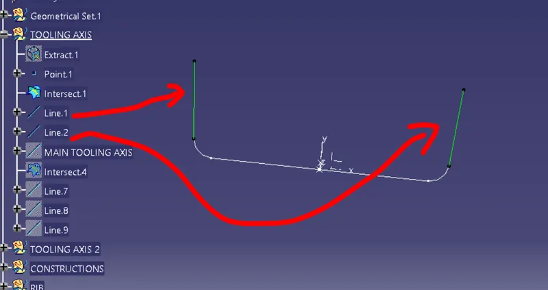
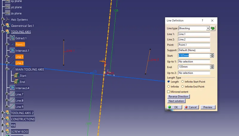
the Last step creates a bisecting line using the 2 lines created, the common intersecting line will be used as the Tooling axis.
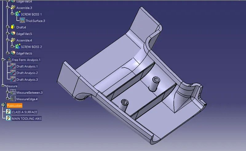
DOOR HANDLE A WITH RIBS & SCREW BOSS
ISO
TOP
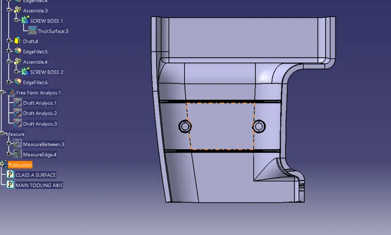
SIDE
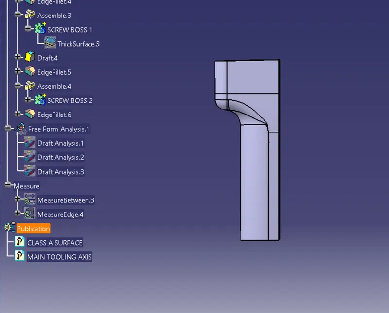
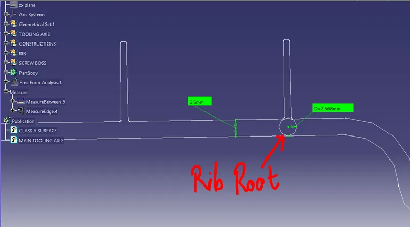
RIB ROOT ANALYSIS
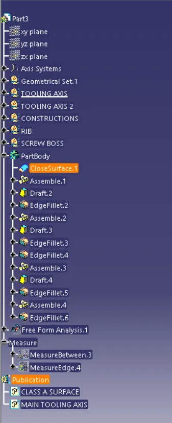
TREE STRUCTURE