Week 9 - Attachment Feature Creation (Ribs & Screw Boss) - Challenge 1
Aim: Create the rib for the Drill Handle considering the design rules mentioned in the video.
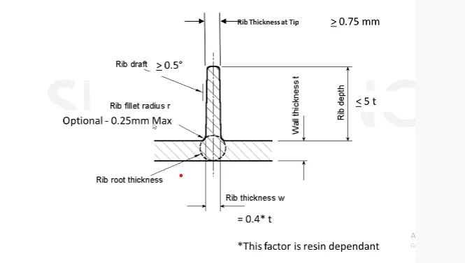
Create the Screw boss for the Drill Handle considering the design rules mentioned in the video.
General Guidelines for Bosses:
- Draft - 0.5 degrees on the walls of boss
- Thickness - Typically 40%* of the nominal wall at the base.
- Height to Diameter Ratio - 3:1
- Radii - 0.25mm maximum radii.
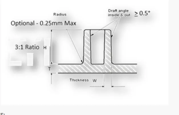
*Draft Angle:-
Draft angle is nothing but providing some tapered portion to the part for easy removal of the component from the mold during manufacturing. This is especially done in the case of plastic component design having a complex shape. Mostly the 3-degree draft angle is provided but it can vary depending upon the component which is to be designed.
Before providing a draft angle we need to decide on the tooling axis also known as the molding axis considering the faces which can cause issues while manufacturing.
*Tooling Axis:-
It Is nothing but the direction in which core and cavity movement takes place.
It is nothing but the direction in which the mold opens and closes the draft angle needed to be provided by considering this tooling axis.
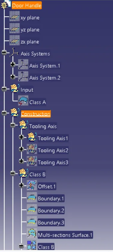
We can create a tooling axis by using 4 Ways.
1.Any of the standard Axis
2.Normal to the any one class A Surface.
3.Bi-secting Method
4.Tooling Axis with class A
*BISECTING METHOD:-
This method is used for the generation of the tooling axis for that purpose first we need to decide the direction of molding and then we create one dummy tooling axis for the reference to the purpose.
In this method, we select the surfaces which can create problems and take intersections in the x and y direction. By using these curves we draw two lines and then draw a bisecting line from these two lines in the x-direction and y-direction.
If it is done in x-direction then it is called a tooling axis clearing x-direction and if in y then tooling axis clearing y-direction.
After completing this we need to draw a final line bisecting this two tooling axis in X and Y direction to get our final output.
Class A Draft Analysis:-
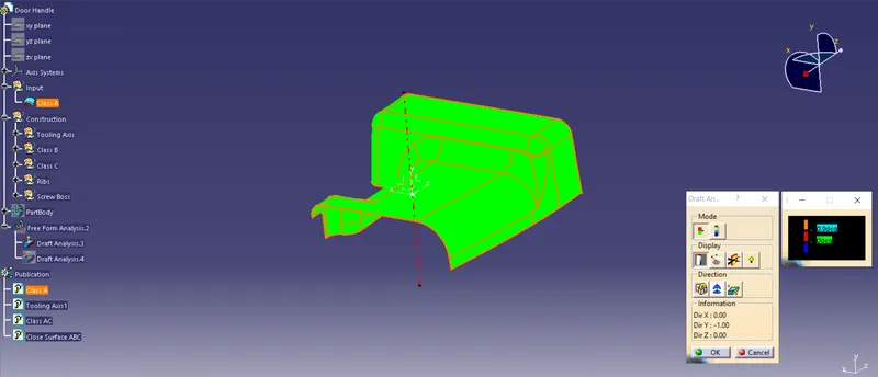
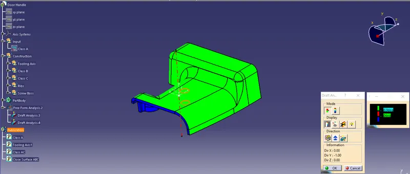
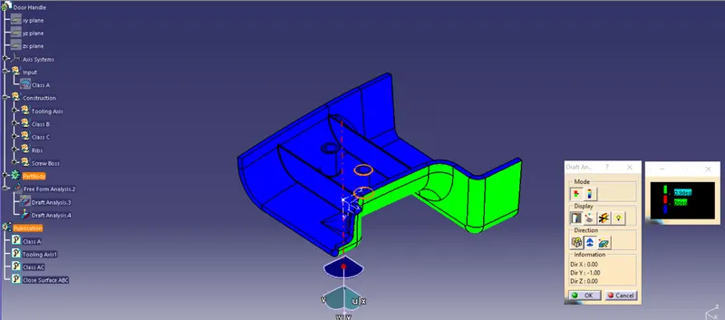
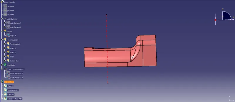
In this Class A is Provided and Draft Analysis is carried out ,Firstly tooling Axis is created with standard Axis.
But Draft analysis did nit get cleared, So we make axis which is normal to any surface . This type also did not clear draft Analysis.
Finally we created axis with bisecting method, But draft analysis did not get clear. It mean their is issue with given Class A surface.
So we decide to work on first type only, but we decrease the minimum draft value upto 0.9 deg. And Analysis get cleared
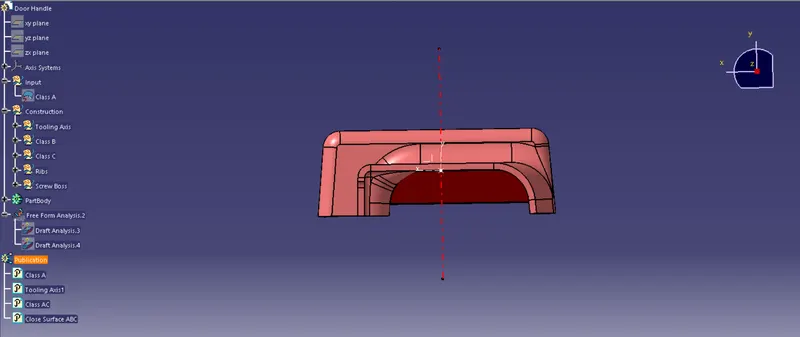
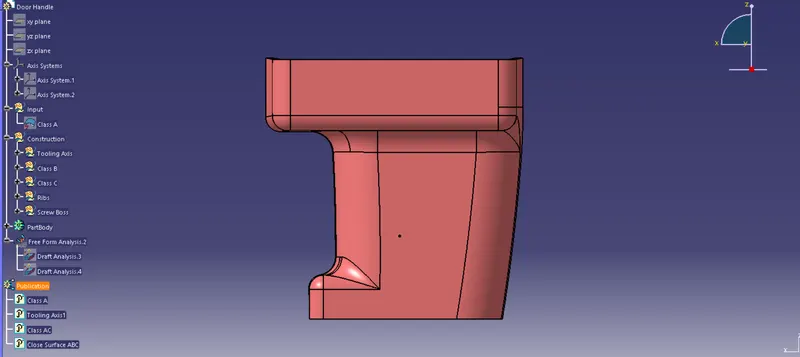
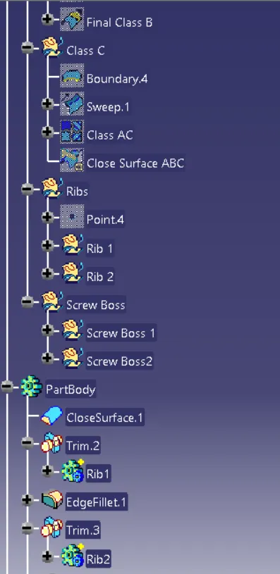
*Closed Surface A,B & C:-
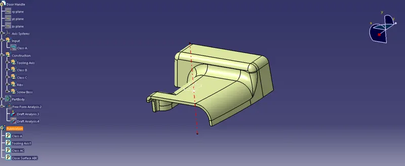
*Closed Body/Solid Model/Plastic Model
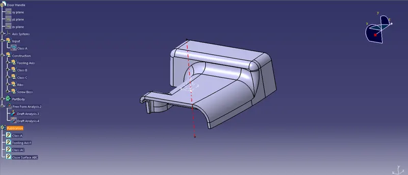
B Side Creation Rib And Screw Boss:-
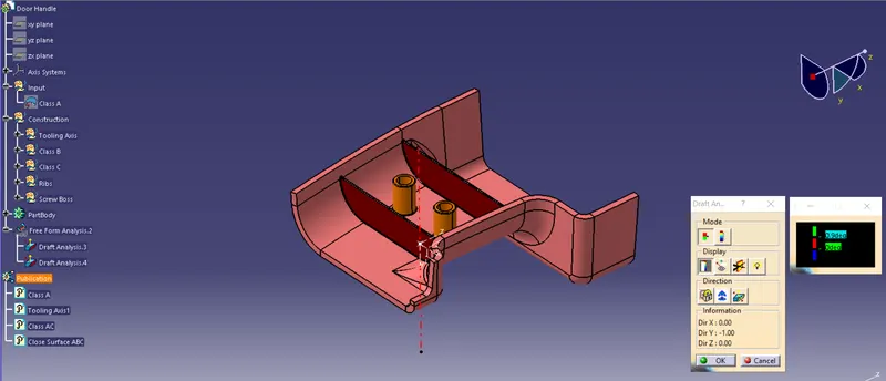
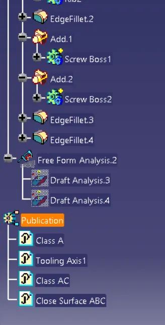
Draft Analysis Model:-