Week 9 - Attachment Feature Creation (Ribs & Screw Boss) - Challenge 1
Design rules for plastic components:
- Nominal/Ideal wall thickness of plastic components should be 3mm.
- Deviation of +/- 30% from the wall thickness is accepted.
- Example for 3mm thickness, 2.1 to 3.9mm thickness is accepted.
- For some components such as the instrument panel, upto 5mm thickness is accepted.
- Ideal draft for a component is 3 degree
- Minimum draft accpeted is 0.5 degrees
- For grained surface (surface finish option) minimum 7 degree draft is preffered.
Major B side features in plastic components of atomotive are:
- Rib Design
- Screw Boss Design:
- Dog house design
Rib Design:
Ribs provide a means to economical and strength in molded parts without increasing the overall wall thickness inturn saving extra costs.
They also serve as:
- Locating and arresting components of an assembly
- Providing alignment in mating parts
- Acting as stops or guides for mechanisms
Rib thickness causes sink marks and in turn cosmetic problems on the opposite surface of the wall to which they are attached. Highly glossy or aesthic surfaces must have thinner ribs.
Proper Rib design involves five main issues:
- Thickness
- Height
- Location
- Quantity
- Manufacturability:
General guildlines for Ribs:
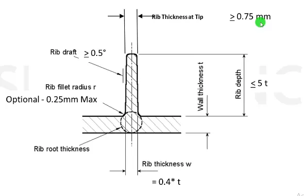
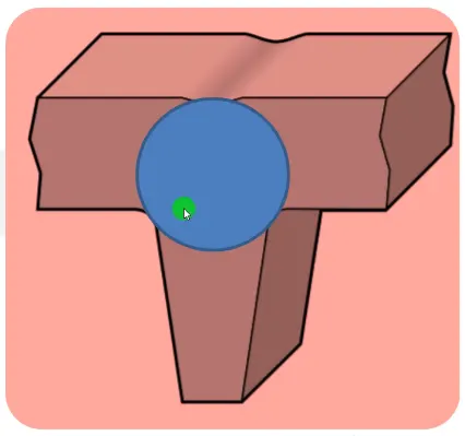
- Draft:
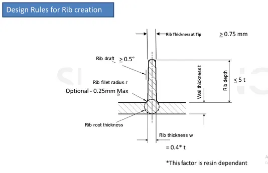
- Optimum draft angle for ribs is 0.5 degree draft per side.
- More than 1 degree of draft per side can lead to excessive rib thickness reduction and filling problems in tall ribs
- Thickness:
- Rib thickness are generally about 0.4 times or 40% of the base thickness. For example we make ribs of approximately 1.5mm for a 3mm thick component
- Rib thickness also directly affects mouldability. Very thin ribs are difficult to fill. Generally, ribs should be not less than 1mm thick.
- Height:
- Height of the ribs should not cross 5 times the thickness of the base component (5T)
- For example: For a 3mm components rib height can be 15mm or less.
- Spacing betweeen two ribs :
- Very tall ribs are prone to Buckle under load. We may consider designing 2 or more shorter, thinner ribs to provide the same support with improved mouldability.
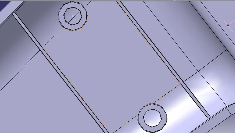
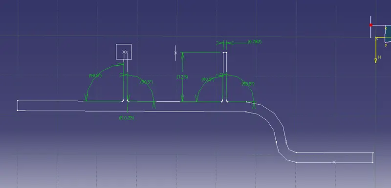
- Height (y) / Distance ratio (x) should be 3:1. For example, for 12.5mm rib height,
distance between two ribs should be 12.5/3 = 4.17mm, approx 5mm. 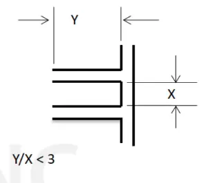
- Thickness at top:
- Minimum of 0.75mm thickness should remain at the top of the rib.
- Minimum of 0.75mm thickness should remain at the top of the rib.
- Optional Radius:
- Rib fillet radius must be 0.25mm maximum, not above that.
- Rib fillet radius must be 0.25mm maximum, not above that.
- Rib root thickness:
- The diameter of rib root thickness should not cross +/- 30% of the thickness of the component.
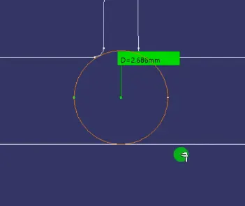
- The diameter of rib root thickness should not cross +/- 30% of the thickness of the component.
- Ribs should be connected to other structural features wherever possible.
Screw Boss:
- Screw Bosses are B side features that act as points for attachment and assembly.
- They mostly ccan be seen as Cylindrical projections with holes designed to recieve screws, thread inserts or other types of fastening hardware.
Design consideraions for screw Bosses:
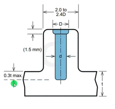
- Outside diameter of the bosses should remain within 2.0 to 2.4 times the outer diameter of the screw or insert.
- Avoid the merging of screw boss to the side walls as they will form thick sections that lead to sink marks. Position bosses away from the side walls and inf needed, use the connecting ribs for support.
In unavoidable circumstances, cosider using an open boss design for bosses near a standing wall.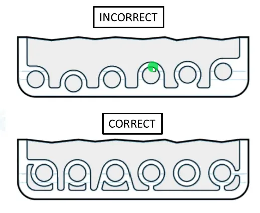
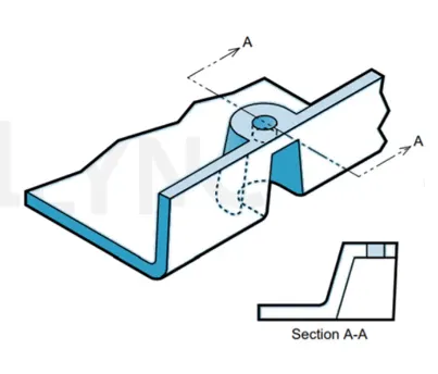
- The Screw should not penetrate more than 0.3 times the thickness into the component.
At the same time, the Boss hole should extend the Base wall level, even tho the full length is not required for assembly. Becasue if not provided it will form thick sections and possibility of sinks or voids.
Fillet radius should also be kept in consideration to avoid thick sections.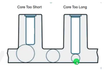
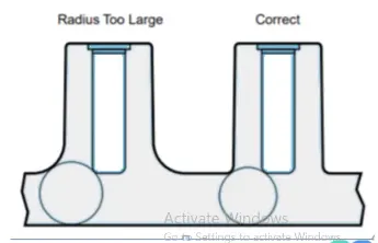
Design rules for Screw Boss:
- Draft:
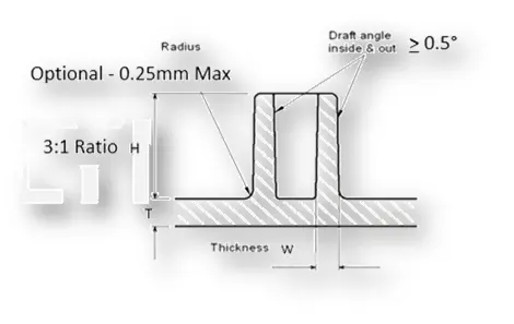
- Minimum 0.5mm Draft should be provided.
- Thickness:
- Ideally the thickness of one side of boss should be 0.6 times of the component thickness.
- W = 0.6*T, It may increase in different cases.
- Outside diameter of the bosses should remain within 2.0 to 2.4 times the outer diameter of the screw or insert.
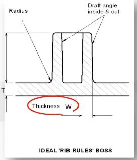
- Optional radius:
- Radius can be 0.25 mm maximum
- Boss Gussets:
- Boss gussets / Ribs must follow the Rib design guideline
- Coring out botton
- Planning ahead for tyoe of ejection
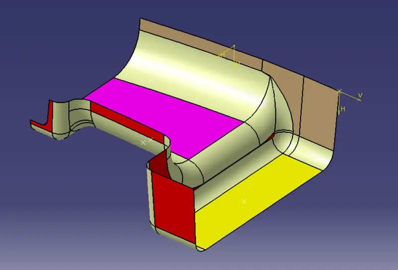
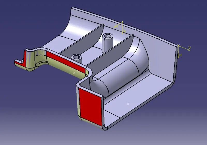
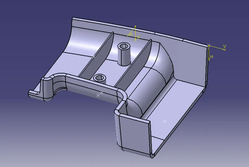
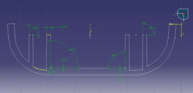
The following Class A was thickened to 2.5mm using proper methodology. ater, Ribs and ScrewBoss were added to B surface as B side features considering the design rules for both respectively.