Week 9 - Attachment Feature Creation (Ribs & Screw Boss) - Challenge 1
DOOR HANDLE:
The initial step is to check for any discontinuity in the class A surface model using Join or Boundary option
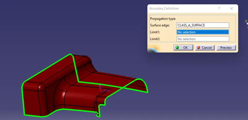
Here only the outer boundary line is found. There is no discontinuity between the surfaces.
The next step is to define the tooling direction.
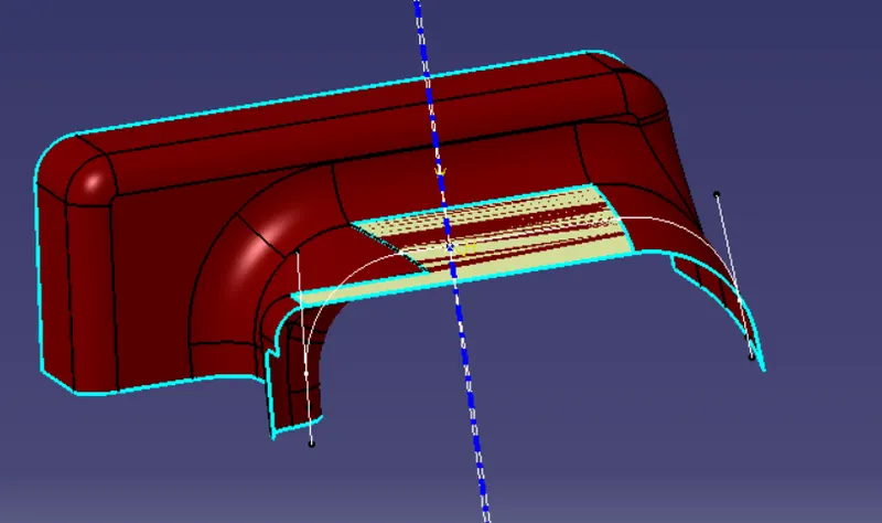
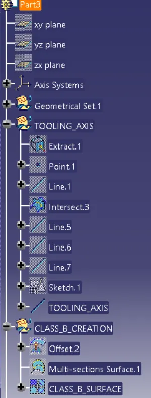
Intersecting the class A surface with the XY plane and extending two lines. Bisecting those two lines to create a reference axis for the Y-direction of the component.
Draft analysis on Class A surface:
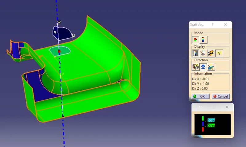
Green color on the class A surface denotes- Draft angle 3 degrees and above
Blue denotes- 0-3 deg angle
Red denotes- Less than 0 degree
Class_B_Surface_creation:
Extracting the faces from class A surface and offset to 2.5mm
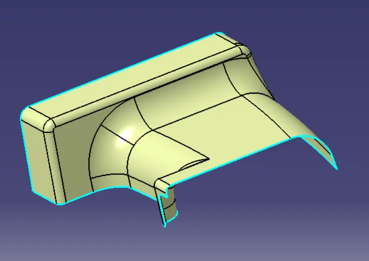
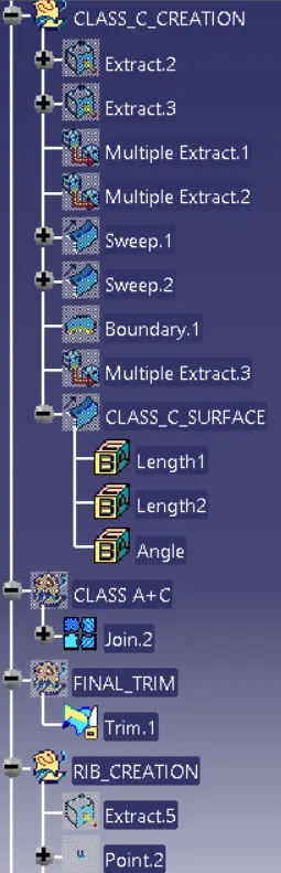
Class_C_Surface_creation:
Class C surface is used to close class A and Class B to form a closed surface.
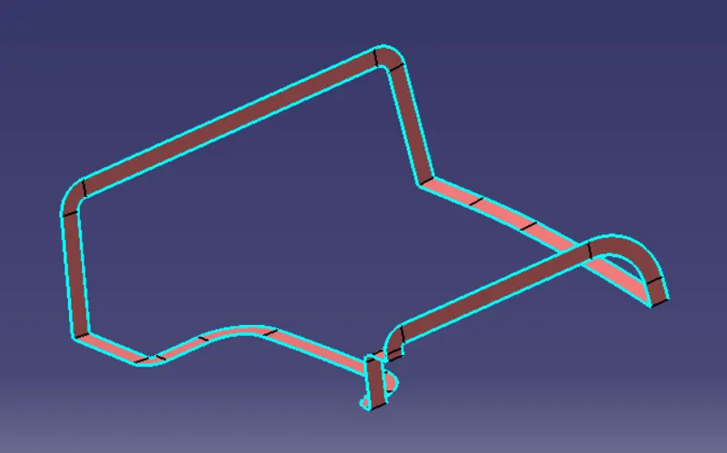
Joining Class A& Class C surface and trim with Class B surface to create a closed surface.
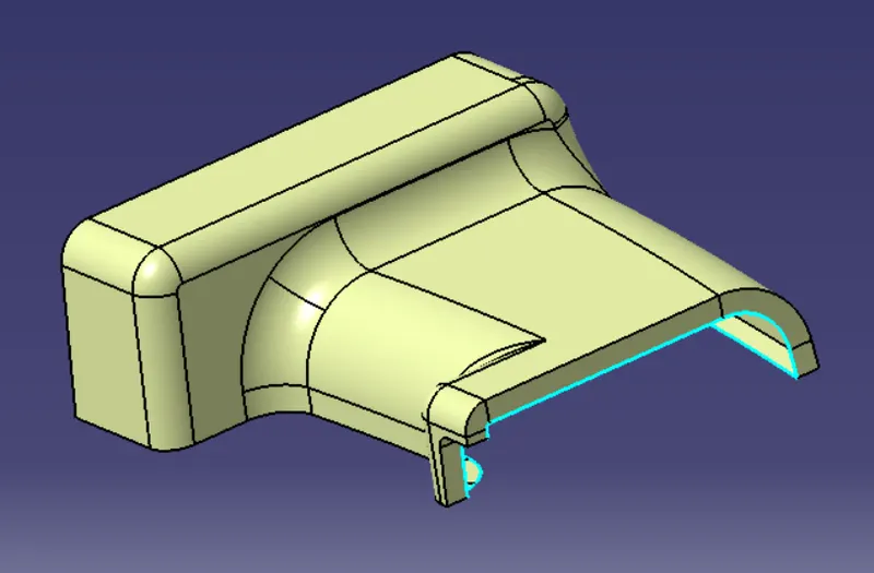
Creating a solid model:
Using the closed surface option in part modeling to form a solid model.
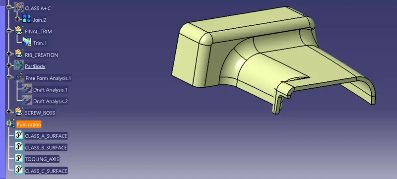
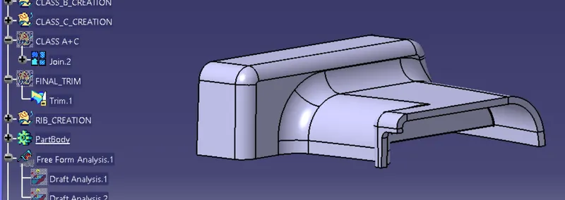
Creating Rib & Screwboss Features:
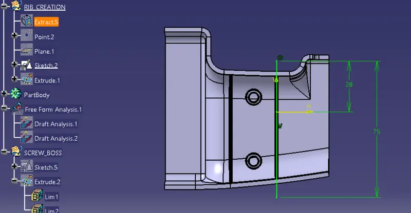
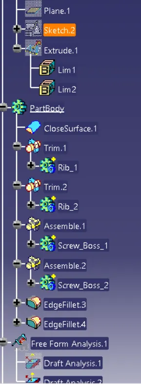
Rib sketch is drawn on a plane. surface is extruded to a height of 12 mm because the wall thickness is 2.5mm. so the rib height should be less than 0.5*wall thickness.
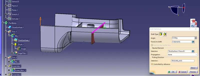
Draft angle of 0.5 is given on all faces. Min draft angle for rib is 0.5 degree.
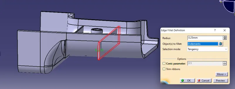
Edge fillet of 0.25mm is given. Edge fillet should not be more than 0.25mm.
After finishing the rib_1 is copied with link and translated to a distance of 25mm.
Screwboss:
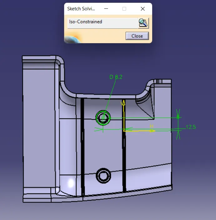
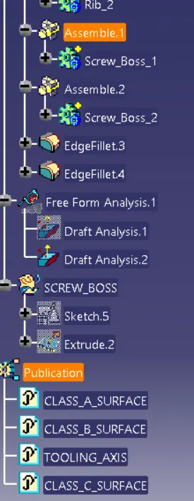
Screwboss extruded to a distance of 12mm. Height to Dia is in the ratio of 3:1. Material thickness is 2.5mm. so 12mm is referable.
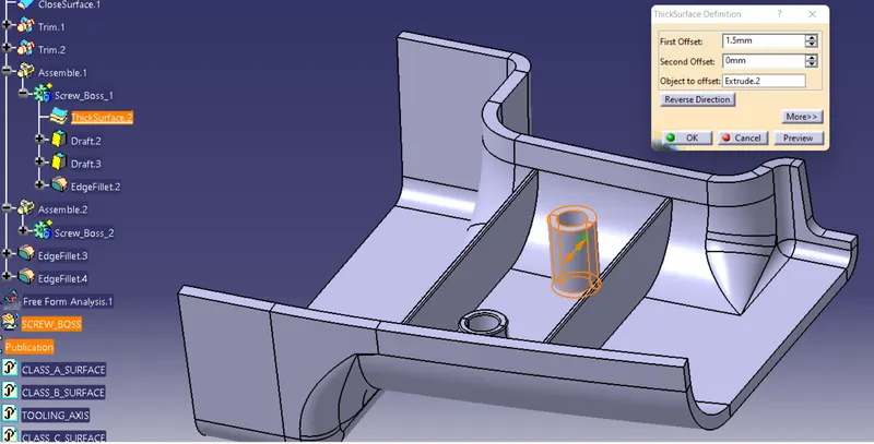
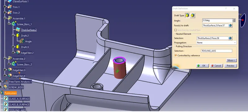
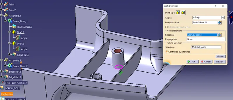
Draft angle of 0.5 degrees is given for both the inside and outside faces.
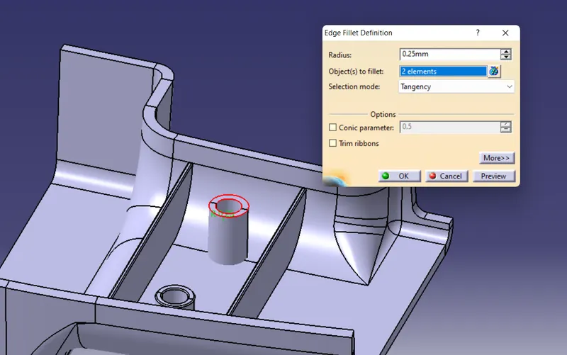
Minimum radius of 0.25 is given.
Screw_boss 1 is pasted with link and translated to a distance of -35mm in x-axis.
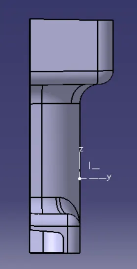
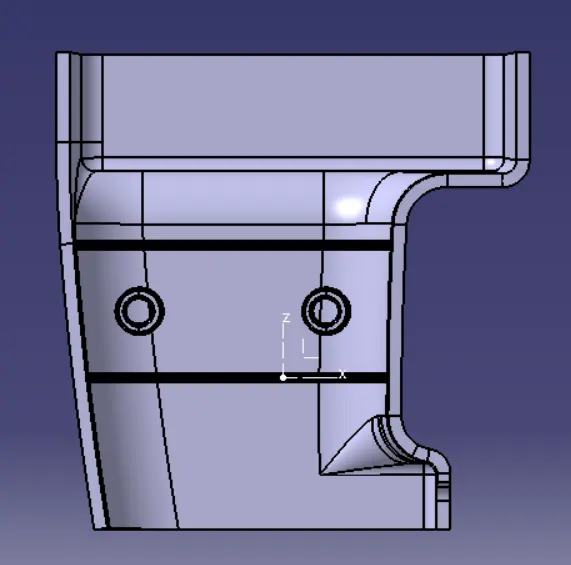
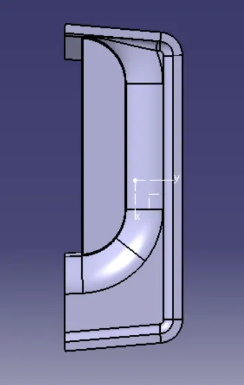
Draft analysis on finished part:
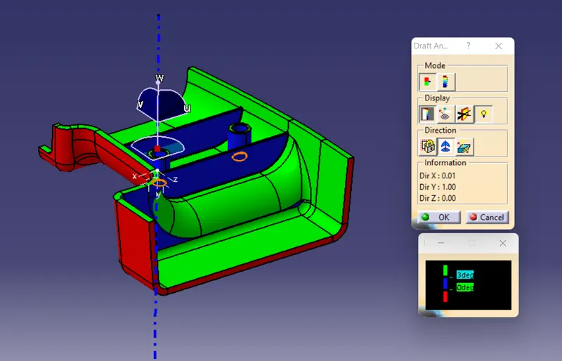
Screw boss, Ribs have a draft angle of 0.5degree so it is highlighted in blue color.