Week 9 - Attachment Feature Creation (Ribs & Screw Boss) - Challenge 1
Objective -
- Create the rib for the Drill Handle considering the design rules
- Create the Screw boss for the Drill Handle considering the design rules
- An explanation should be given on the way of creating the tooling axis, particularly the Bisecting method.
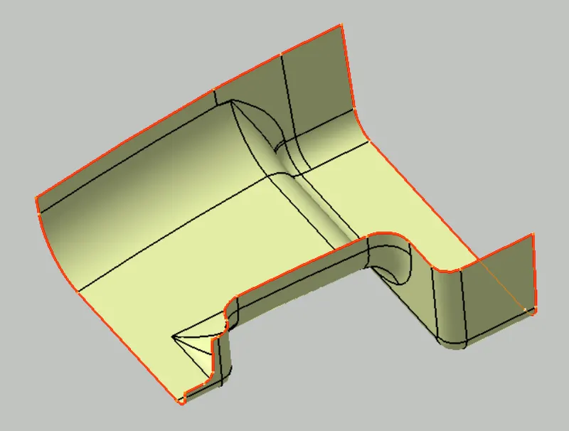
Step 1: Analysis of Class A surface to check irregularities with help of Boundary command.
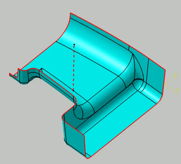
Step 2: To create Tooling axis by using Bisection method.
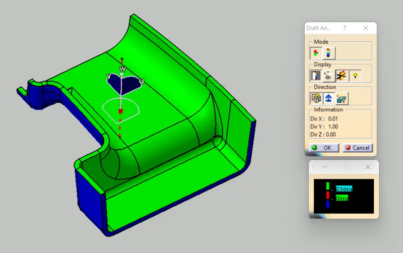
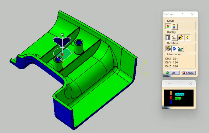
Step 3: Perform a Draft Analysis on Class A surface
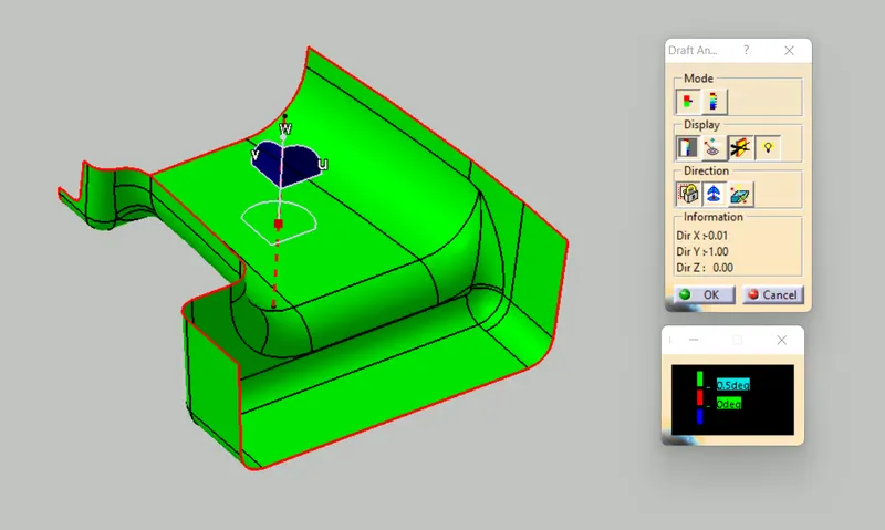
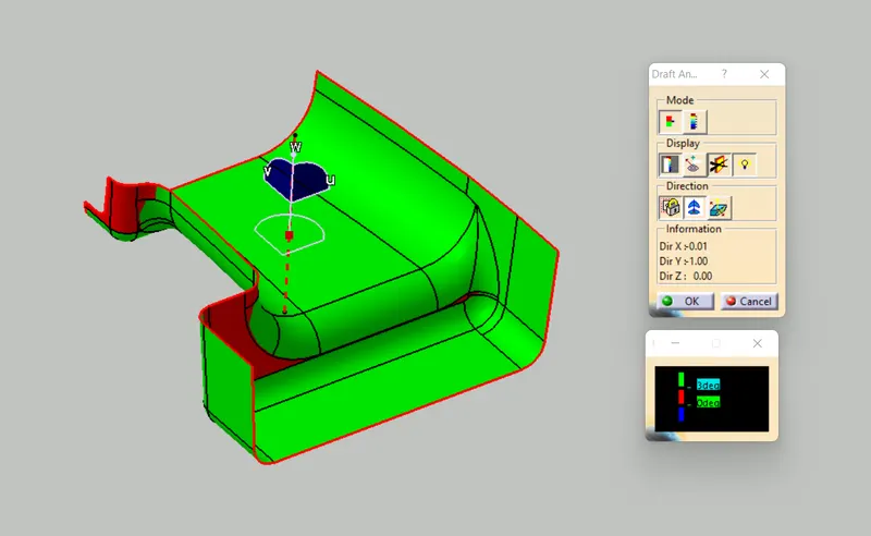
Set the range for draft angle 0.5 degree. Means if the draft angle is zero then it shows red colour, If draft angle is in between 0 to 0.5 degree it shows sky blue colour, If draft angle is more than 0.5 degree then it shows green colour.
Step 4: Creation of Class B surface.
By offesetting class A surface to 2.5mm (which is thickness of part) and fill the patches which is created during offset.
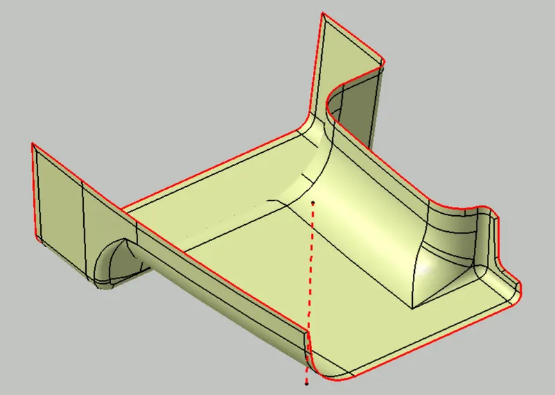
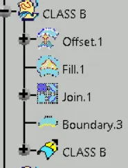
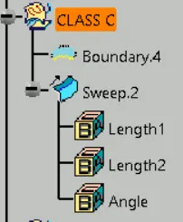
Step 5: Creation of Class C surface.
By using Sweep command created and whith respect to Class A surface boundaries.
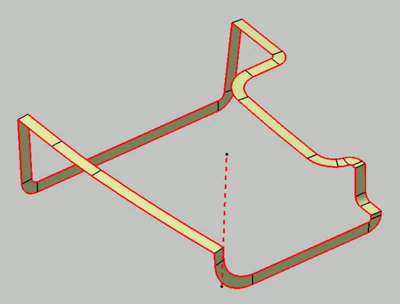
Step 6: Join class A and C surface to form a close surface.
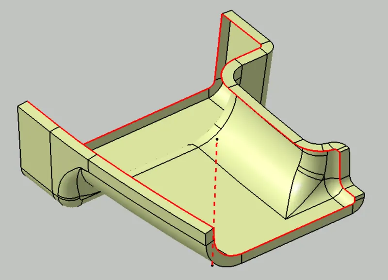
Then Trim Class B surface with Join of Class A+C.
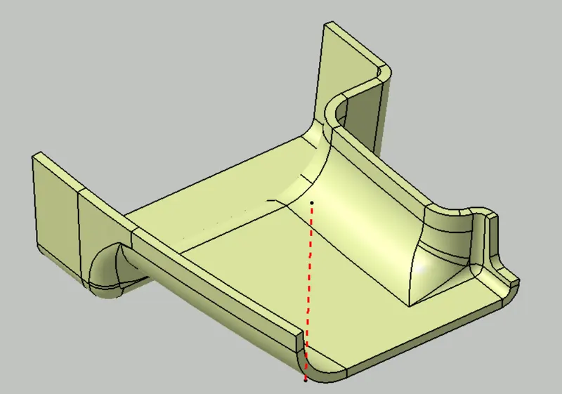
Step 7: Create solid body by Closed surface command in part workbench.
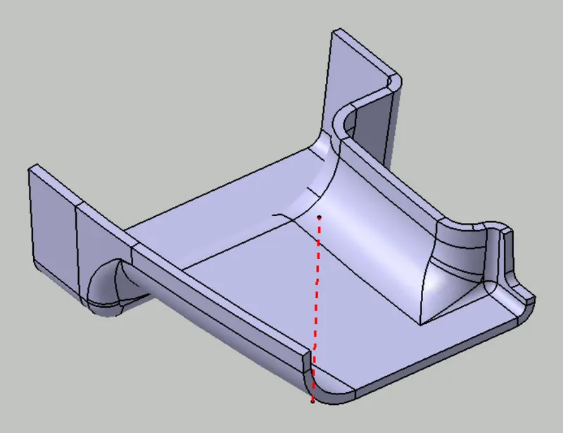
Step 8: Creation of Rib with Rib design rules.
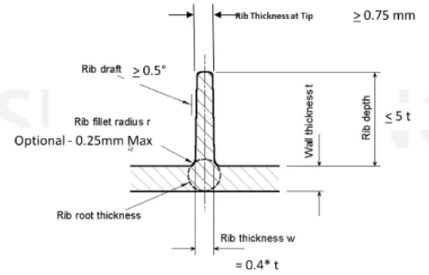
Thickness = Thickness of rib is 0.4*t ; t = thickness of part.
Draft angle = 0.5 degree on each side
Height = Hieght of the rib is 5*t or 5 times of part thickness
Rib thickness at top is greater than 0.75 mm.
Rib fillet radius = 0.25 mm
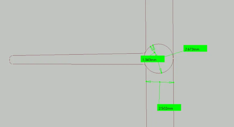
Rib root thickness =
Distance between two ribs = 2*t
Designing of both ribs by following same considerations
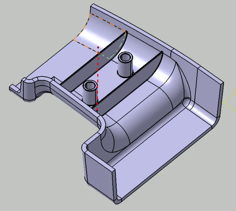
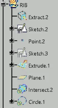
RIB root thickness analysis
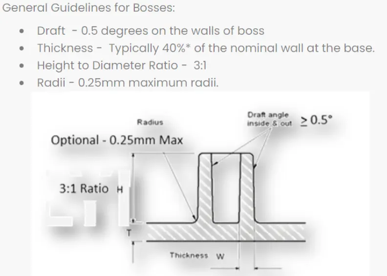
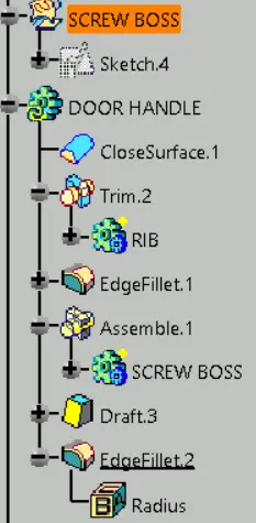
Step 8: Creation of Screw Boss
Conclusion - Hence created a design features like RIBS and SCREW BOSSES Succesfully.