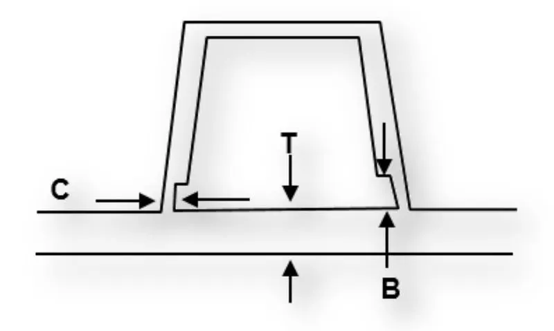
Week 9 - Attachment Feature Creation - Challenge 2
TITLE: DOOR TRIM - Engineering Feature - Dog House
-
→ Aim:
To create surface B with the thickness of 2.5mm and surface C with considerable draft angle for the given surface A, and to create engineering feature of Dog House following their standards respectively.
-
→ Material:
Door Trim Panels of automobiles have been made of a combination of Modified Polyphenylene Ether (PPE). It's also well-suited to heavy-duty applications, so it can be used for automotive body parts, too. Plastic used in cars, like PPE, helps the body absorb and redistribute energy during an impact, keeping passengers safe. And also completely aesthetic.
→ Tooling axis:
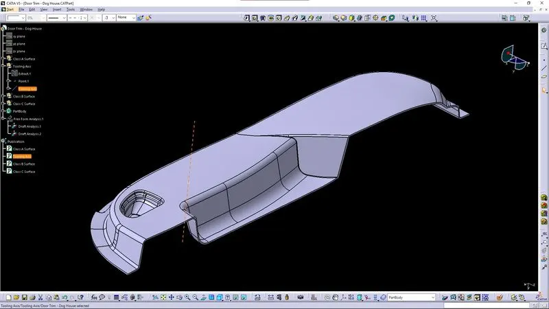
When a plastic body is created in a molding, the cavity and the core is moved respectively to one another. The plastic component is poured and ejected respectively to that axis of the core and cavity motion. This axis is called as "tooling axis". For the challenge to be satisfied, the discussed tooling axis must be created for the product, keeping the motion of core and cavity in mind.
To Add Tooling Axis:
- An visual analysis by us to be undertaken at every axis plane of X,Y and Z to come up with the suitable plane that holds all the features of the surface A.
- Here the X and Z axis, doesn't suit the above requirement, hence moving to Y-plane we preserve majority of the details given to surface A.
- At first we must create a geometrical set, where it should be renamed as the "Tooling axis".
- To Fix Y axis as the tooling axis, we must construct line to represent it.
- For the line creation, we can use the hole present in surface A as the reference and using the point option, we must include a point in the centre of the hole.
- Now to draw a line, use the line-direction command, where the previously created point as the starting end, we must extend it on both the sides for a considerable distance, with Y-axis as the direction.
- Now to comfortably view the final tool axis, we must publish it separately using publish command in the tools option in CATIA.
Tooling axis:
-
→ Class A Surface:
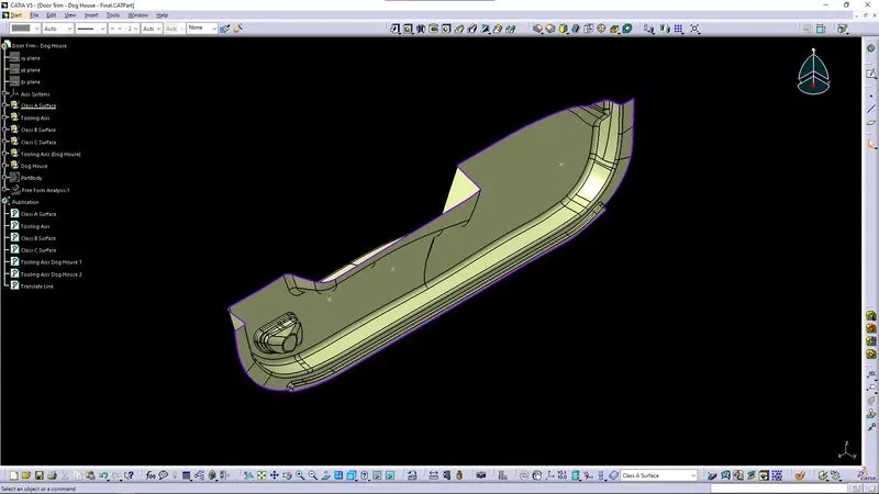
Starting with the Class A as the input, and required output as the plastic component, we should consider the following rules:
- The Surface A being the aesthetic part of the plastic component, whatever surface created must not alter the original surface A.
- The Draft angle must be on the surface C.
-
Class A Surface:
→ Draft Analysis:
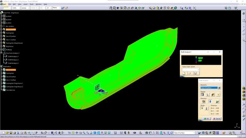
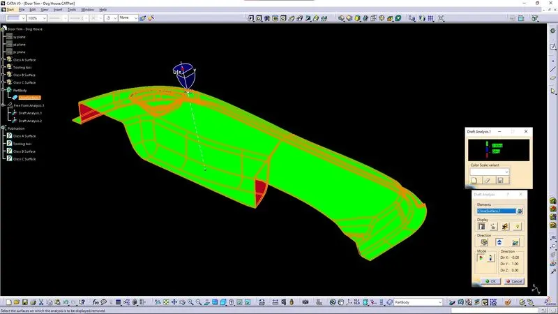
When the final component created, the drafting analysis done to ensure the draft angle given to the surface C is within the standard range of 3 degree. By keeping this angle, the part produced are safer to be ejected by the ejector pins, without being damaged. The color order of GBR (i.e., Green, Blue, Red) discusses whether the draft angle is safer in limits,
- if it is green, then the draft is within 3 degree
- if it is blue, then the draft is not less than 0 and not more than 3 degree.
- if it is red, then the draft is less than 0.
To Analyse - Drafting Analysis:
- Add material using the view option to let the draft analysis to run.
- Select the surface or final part body to make it highlighted in the feature tree.
- Use the analysis in the insert option in the CATIA's menu bar, to find the Feature draft analysis.
- Now after selecting the option, two pop window will be displayed, where:
- One has the colour coding, where we must define the colors in the order of GBR (Green, Blue, Red) respectively and set the angle value to be 2.9 for Green, 0 for Blue, and less than 0 as Red.
- Other pop up has several tools for draft analysis, Now from the right most corner of the screen, drag the direction compass and place it on the tooling axis, where the resulting compass aligns with the tooling axis. Now after it gets aligns, lock the compass position using Compass Lock tool.
- To view the draft analysis, select the Surface or final closed body. By choosing it as mentioned, the analysis produces the color coding over the parts where the draft condition/angle satisfies as we mentioned.
Draft Analysis:
- Draft Analysis - Class A Surface:
- Draft Analysis - Closed Body:
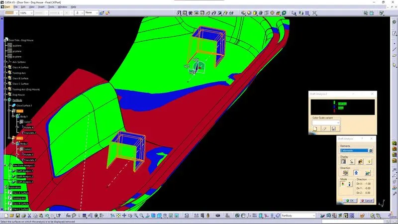
- Draft Analysis - Closed Body with Engineering Features:
-
→ Class B Surface:
The Class B surface is the other side of Class A surface of the plastic component and where the portion sits on the core.
Make Class B as the sacrificing portion of the component at the core, we ensure the ejector pins motion to push the finished component out of the mold to fall on Class B, again saving Class A from the stress created by ejector pins.
To Create Class B Surface:
- Study the Class A surface features by using vernier measure tool to distinguish between the flat and curved surface, by the symbol appears next to it.
- Extract the flat ones by using extract command and leaving behind the curved unelected.
- Now offset the extracts by using the thickness value 2.5 as the offset and now use the untrim command to derive the untrimmed surfaces from the offset.
- Due to the lack of intersection, we must use extrapolate tool by point continuity to make them intersect with each others respectively.
- Now trim the required parts and save in separate geometric sketch.
- Give the fillets to the intersecting corners as per the Surface A but, following the Fillet offset rule, where the bulging upward fillets value must be reduced by thickness and vice versa for the building downward fillet.
- Now the Class B surface is created successfully.
Class B Surface:
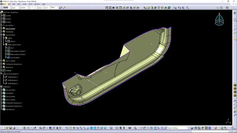
-
→ Class C Surface:
- The Class C surface is the in between portion of Class A and Class B, where the volume is added or in other words, plastic thickness is given here.
- The Class C Surface is given the draft angle of 3 and 90 degree.
- To make the component to be easily ejected from the mold, it requires 3 degree draft angle and 90 degree draft angle is given to cut the surface A and B.
To create Class C Surface:
- Use the Class A surface as the reference and extract the boundaries individually on every sides where the curvature changes using boundary tool with tangent continuity.
- Now use the "swept tool" and "with draft directions" to extrude the boundaries and tooling axis as the guidelines and with draft angle as 3 degrees in outward direction for the holes that intersecting the surface B and for other give 90 degree to cut it right angle..
- Now use the extrapolate tool to intersect the swept extrudes by selecting the unintersected edges of the swept extrudes to intersect with adjacent swept extrudes.
- Use the trim to join the swept surfaces.
- Now do the same approach of sweeping the holes by taking the reference as the boundary using boundary tool with same dimensions, with only change giving the draft inwards to the surface A.
- Save it in a separate geometrical set.
Class C Surface:
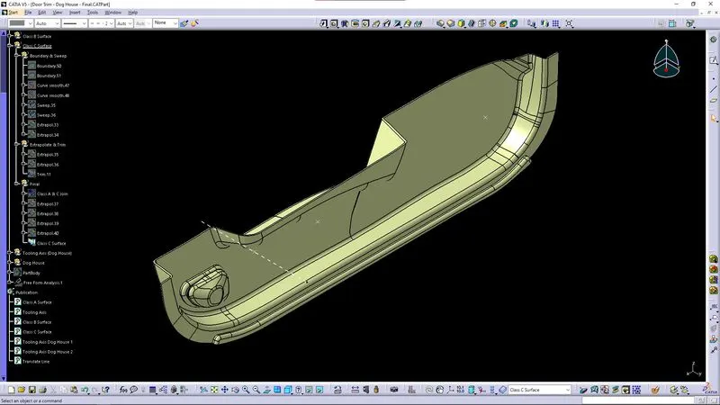
-
→ Final Trim:
- The resulting surface being formed after joining the Class A, B and C as per the above spoken features specific to the surfaces respectively is done in Final trim.
- This showcases the cavity's and core's design of how the mold should be created.
To create joined Class A, B and C Surface (closed):
- Use the join command to join the Class C surfaces of boundary and hole swept extrudes with Class A.
- Use the trim command to trim the extended edges of the class C with Class B.
-
Engineering Feature - Dog House:
To attach the engineering feature Dog House, a separate part is created in the Part Design Workbench using the guidelines to develop one.
- The dog house is developed by sketching a square 35mm x 35mm, keeping the axis as the center.
- Then, the sketch is padded using the "Pad" option, the padding is done by 20mm in a mirrored extent.
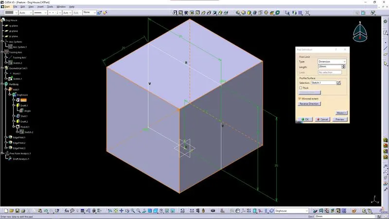
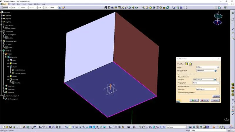
- The padded body (Pad) is then drafted by 0.5° to the three sides (Left, Right, Rear) and the neutral face is the bottom face.
- Keeping the Pulling Direction same as the bottom face directing upward.
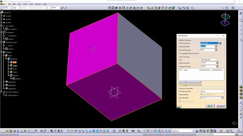
- The drafted solid required a hollow body, here "Shell" option is used to create a hollow body by outer thickness of 2.5mm and inner thickness of 1mm.
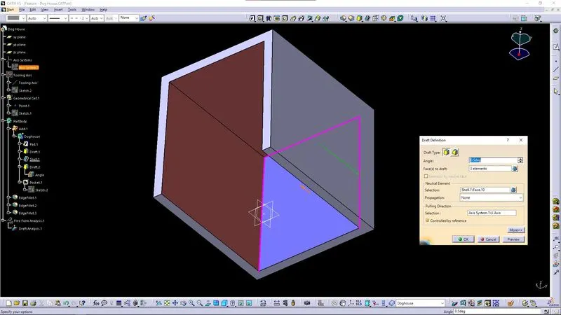
- The hollowed (Shell) body is then drafted by 0.5° to the three inner sides (Left, Right, Upper) and the neutral face is the rear face.
- Keeping the Pulling Direction same as the rear face directing frontward.
- After the creation of a hollow body, the dog house has a guideline to create a cutout in the lower and inner end. So, a sketch is drawn to carry on with "Pocket" option is create that cutout.
- The "Pocket" option fulfills the guideline. The depth of the pocket is 3mm
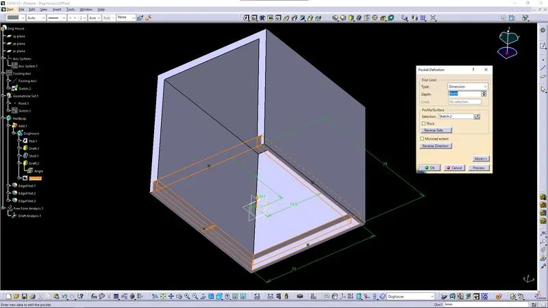
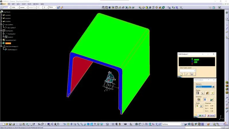
→ After the creation of Dog House, Draft Analysis is done on both the inner surface and outer surface.
- First, the Draft Analysis is done on the Outer Surface which has a draft of 0.5°.
-
- Lastly, the Draft Analysis is done on the Inner Surface which has a draft of 0.5°.
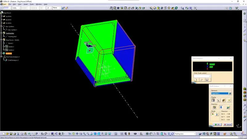
Solid Body:
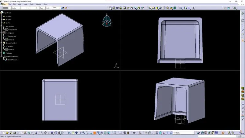
-
- The Dog House part is then copied to the Door Trim part. By copying the partbody, the part is flexible to be placed in the desired file.
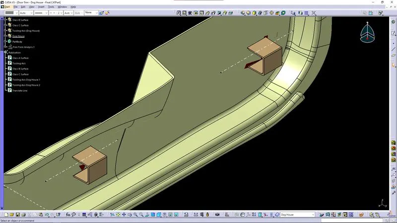
- After copying the partbody of doghouse into the door trim file. Using the "Translate" option, the doghouse part is placed on the door trim part by keeping the starting point of the Doghouse and ending point of the Door trim by specifying the point on the door trim. This operation is carried out once.
- For the second doghouse placement, using the "Translate" option keep the first doghouse as the starting point and the ending point as the desired point.
- After placing both the doghouse features, use Add and Union Trim to place the features on the Door Trim by Boolean operation to obtain the final trim.
-
Final Trim:
-
→ Solid Body:
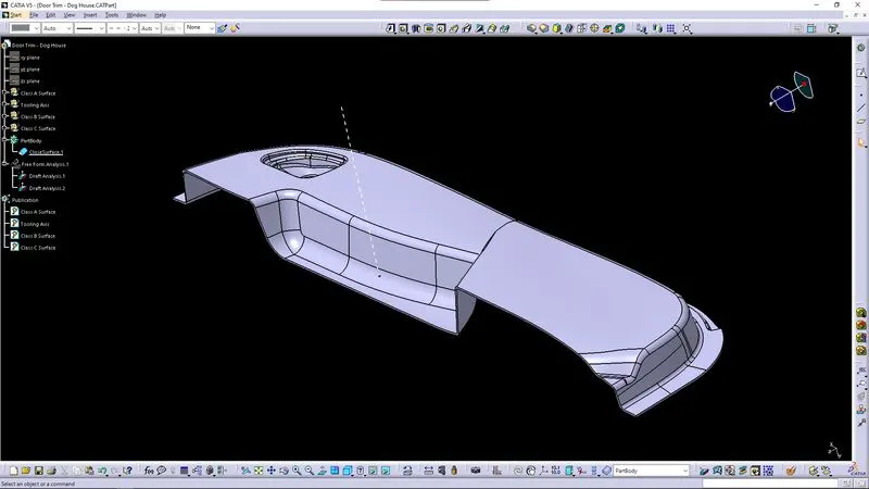
Solid body is the part body created after calling the closed surface command on the Final trim surface.
To create Closed part body:
- Use the closed body tool in part design to create the part body.
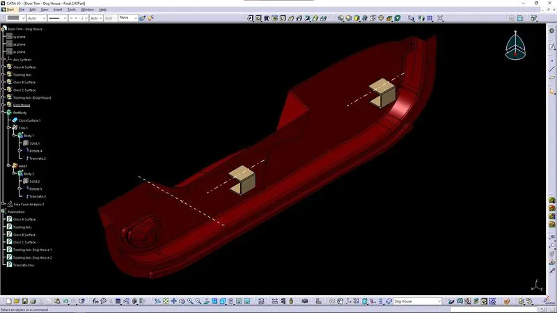
- Run Draft analysis using feature draft analysis from tools, and selecting the part.
Solid Body:
-
-
Doghouse:
- Dog houses are used as supporting feature. Sometimes other engineering features like snaps; locators etc. are mounted on them to increase their strength.
- Dog houses are subjected to draft analysis to prevent breakage or sink marks in the component during ejection from mold cavity.