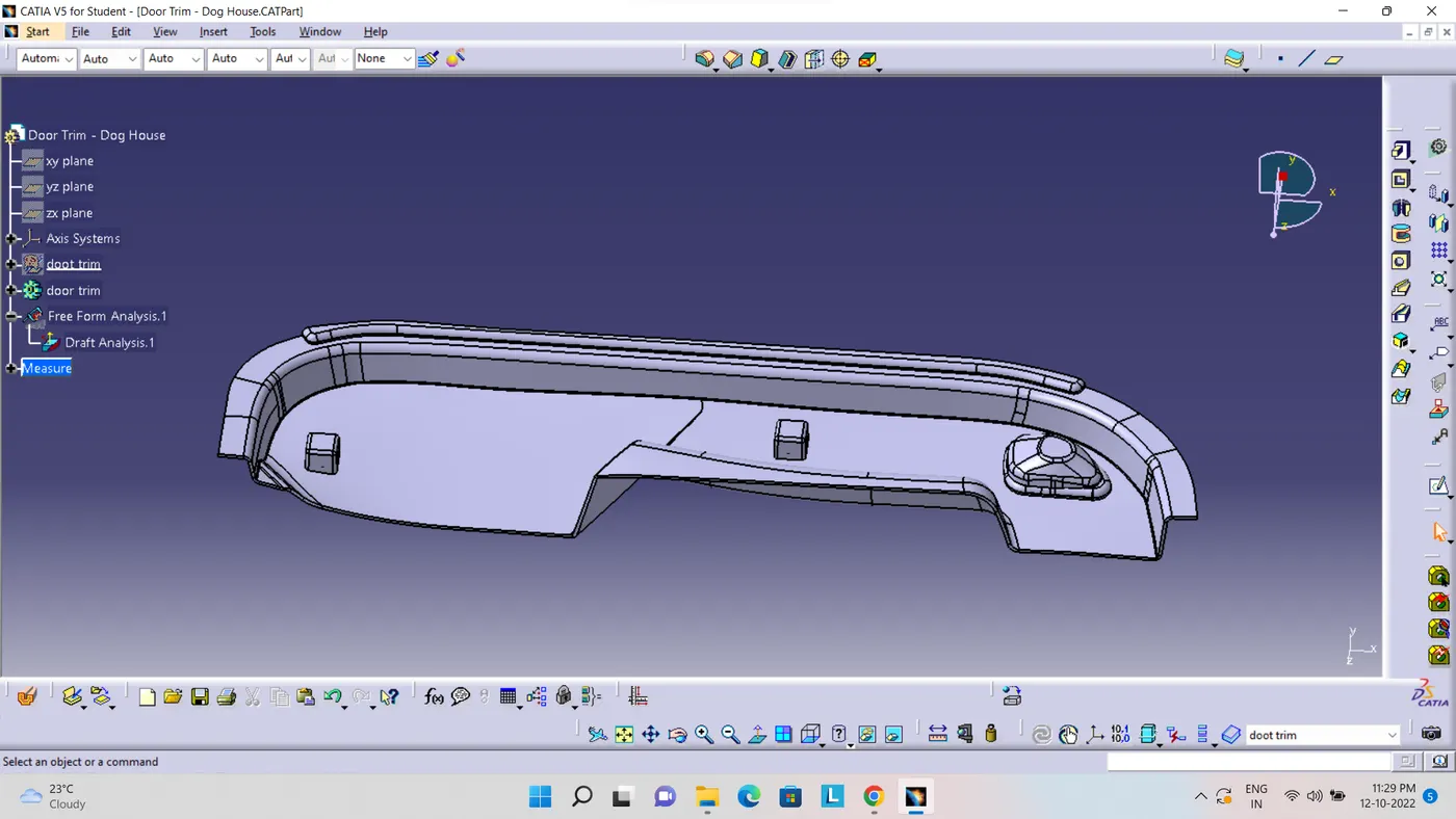
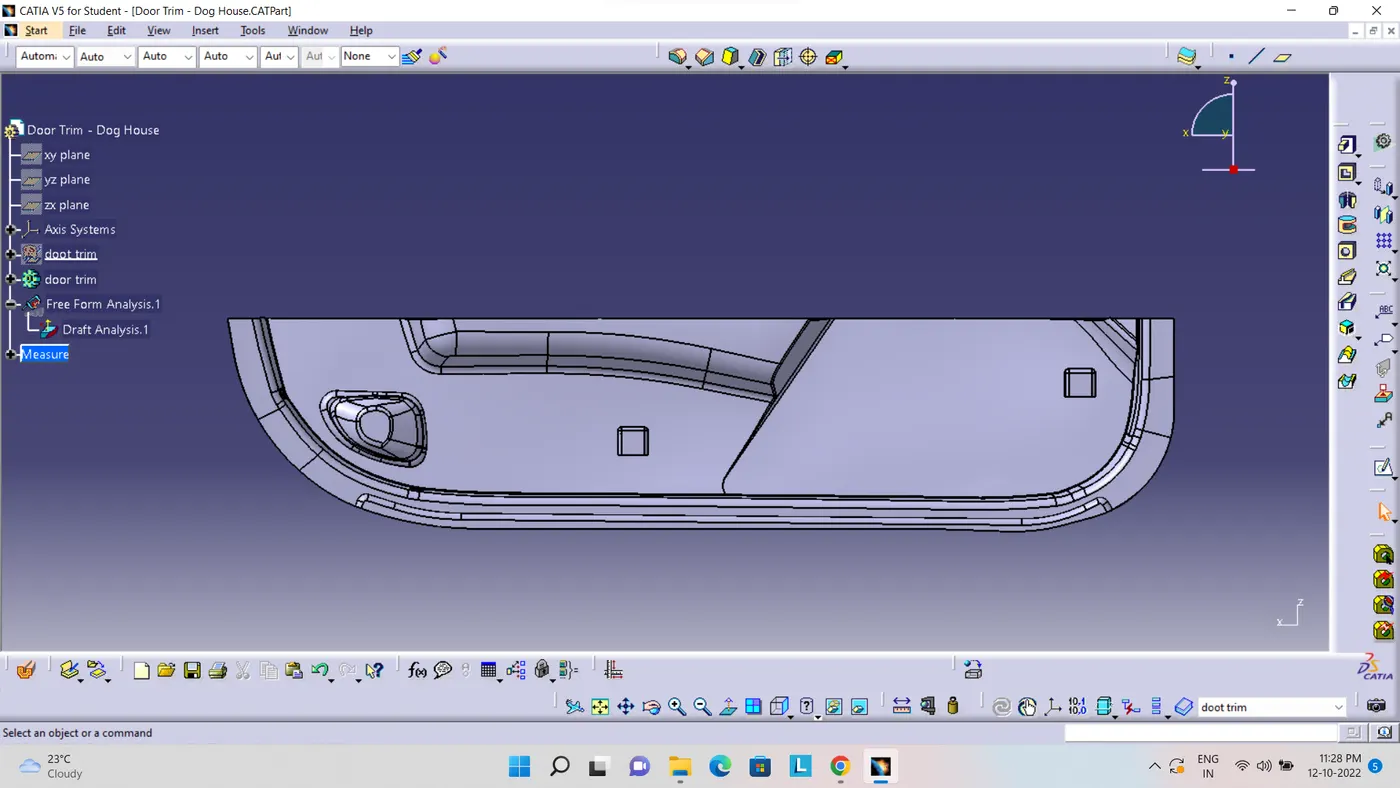
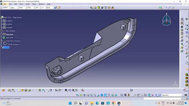
Week 9 - Attachment Feature Creation - Challenge 2
CREATING TOOLING AXIS -
The Tooling Direction is basically the direction that the mold pulls a part. The mold is built in two separate pieces, basically. You have a Cavity side and you have the Core side. The Core pulls apart from the Cavity and that's the Dye line or the Tooling Direction.
- Open the given CAT part file.
- Check for gaps between surfaces for that click on join and then preview.
- If there’s any gap between the surfaces join them with a maximum tolerance of 0.003 mm.
- Extract the boundary and dissemble the boundary.
- Find the correct tooling axis where the material doesn’t interfere with the tooling axis and all the elements can be created.
- Intersect the y z plane with respect to the class A surface.
- Hide the class A surface and create point to point lines on the suspected drafts.
- Create bisecting line with the two lines and point to create a tooling axis.
- BISECTING LINES were used to get the exact medium from the two sides so that maximum positive draft angle can be achieved.
DRAFT ANALYSIS
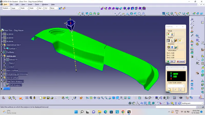
The Draft Analysis command enables you to detect if the part you drafted will be easily removed. This type of analysis is performed based on colour ranges identifying zones on the analysed element where the deviation from the draft direction at any point, corresponds to specified values.
- Before going to drat analysis go to customized view parameter >under mesh >check material and then click ok.
- Now for draft analyses go to insert » analysis » feature draft analysis.
- Use the compass to define the draft direction.
- In the colour scale change the draft angle to 3 degrees.
- The component changes to green in indication of passing draft angle.
- Use running point to check the angle on the component.