Photo Realistic Rendering
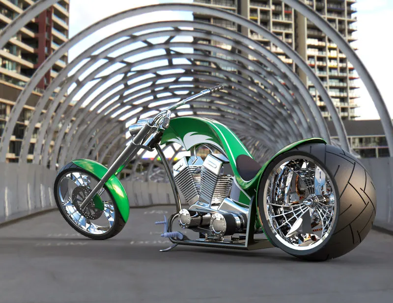
DESIGNING AND RENDERING OF AMERICAN CHOPPER
OBJECTIVE
To design and render American Chopper using Solidworks and Solidworks Visualize and to learn the different tools and operation in Solidworks.
INTRODUCTION
The report contain all the details about the designing and rendering to individual part making to the final rendering. All the tools used and commands used are explained here.
PARTS
The chopper consist of the following parts.
- TRANSMISSION BELT
- KICKSTAND
- REAR FENDER
- CHAIN
- PEDAL
- FRONT WHEEL
- REAR WHEEL
- OIL TANK
- FRONT FORK
- CHASSIS
- ENGINE
- GAS TANK
All the parts are designed individually and assembled together to make the final model of American Copper and rendered it to get the final results.
Each the parts are designed on a weekly basis for making different parts different tools are used. Each parts are designed in a easy and most efficient way.
Parts made and tools used in each week
FIRST WEEK :
The first week classes are about the introduction to solidworks and modelling of the simple parts on the chopper. The parts are modelled in the first week are
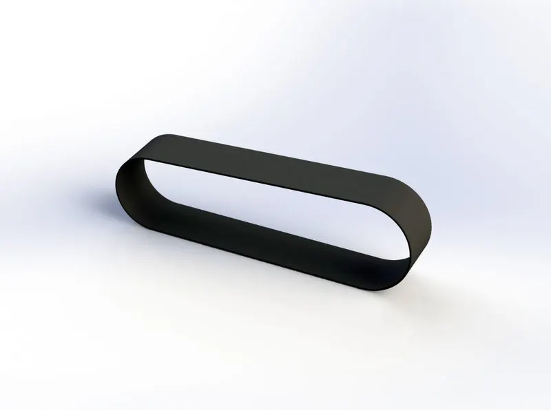
- Transmission Belt
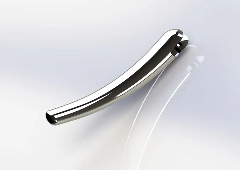
- Kick Stand
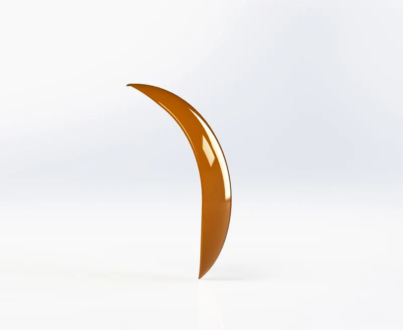
- Front Fender
Many simple tools and commands are used while modelling these components.The main commands(tools) used are.
- Sketch
- Boss Extrude
- Fillet
- Loft
- Dome
- Extrude cut
- Split
- Revolve
- Trim
- Dynamic mirror
- Appearances
- Offset
These all are the basic tools in solidworks so all the basic tools and commands are introduced in the first week itself.
SECOND WEEK :
In the second week classes new tools and commands have been introduced and designed more difficult parts. The parts which are designed in the second week are
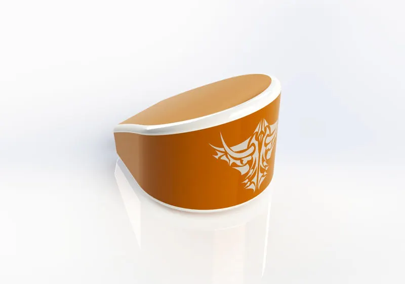
- Oil Tank
- Chain
- Pedal
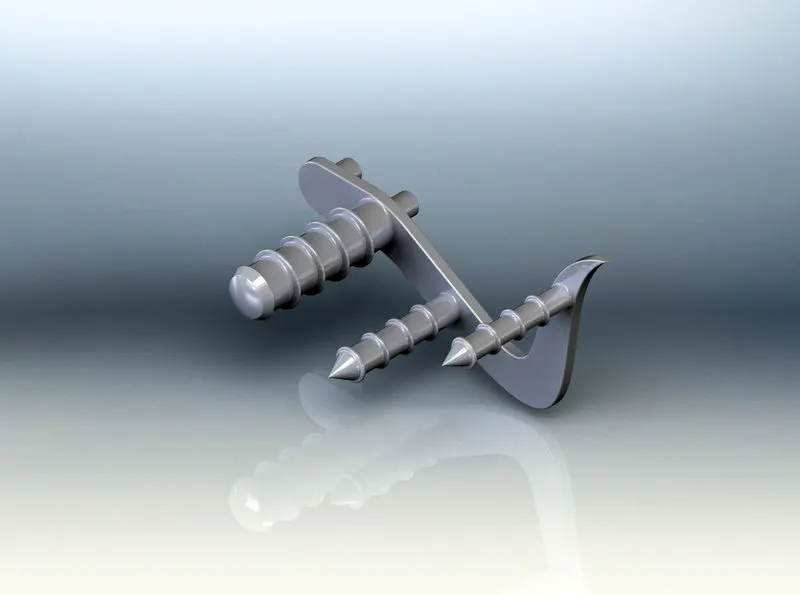
For making the oil tank first created two parts and then combined .The shell feature also used to create the space inside the tank
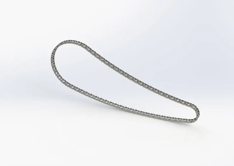
Chain is one of the most diificult parts that maked in the chopper designing. By using the new block feature in the solidworks the design has become easy.
The commands and tools which are used while designing these parts are
- Sketch
- Trim
- Blocks
- Mirror
- Patterns
- Combine
- Shell
- Spline
- Linear pattern
- Chamfer
These are the main tools used. While designing these part we become more familiar with the tools and commands.
THIRD WEEK:
In the third week classes new tools and commands have been introduced and. The parts which are designed in the third week are
- Front wheel
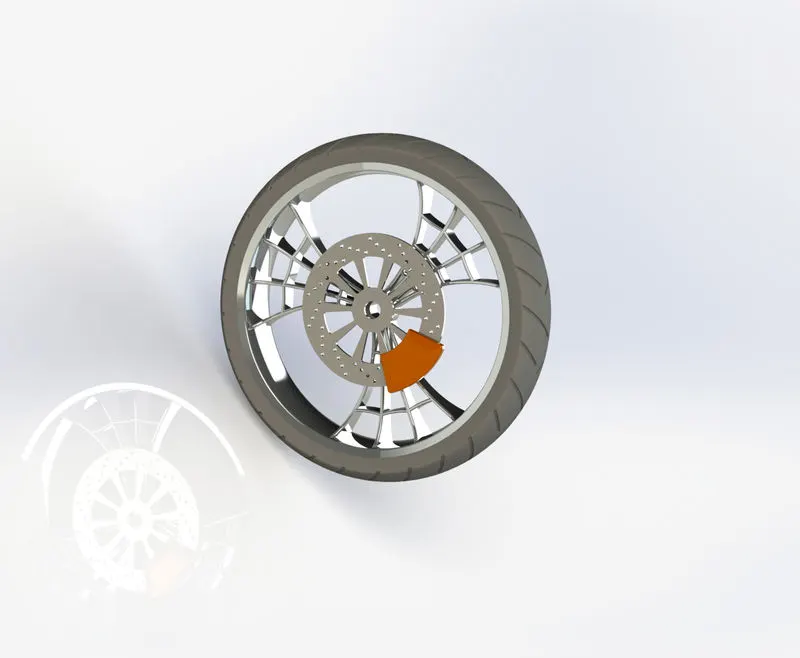
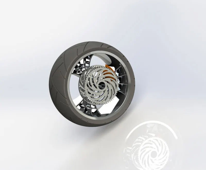
Parts like tyre, wheel, calipper, break disk are designed in this and combined and by using tools like circular pattern and revolve the designing become much easier. By using all this created a web like front wheel and good tyres.
The main tools which are used in the designing process are
- Revolve cut
- Circular pattern
- Extrude
- Cut extrude
- Fillet
- Chamfer
FOURTH WEEK:
In the fourth week classes new tools and commands have been introduced and. The parts which are designed in the fourth week are
- Rear wheel
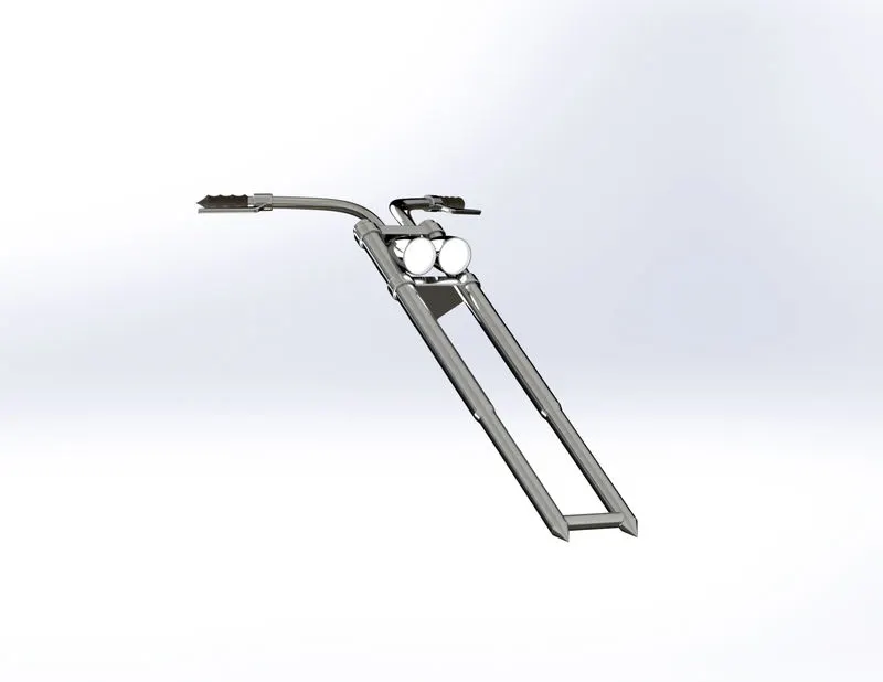
- Front fork
The rear wheel also have the same commands as the front wheel but in rear wheel a chain sprocket is created.
In the designing of the front fork one part is created then mirrored the projected curve tool is really helped in creating a good finished product . The lights are also given to headlights to get a realistic look.
The tools which are used in designing these are
- Extrude boss
- Revolved boss
- Dome
- Projected curve
- Mirror
- Planes
- Combine
- Fillet
- Chamfer
- Appearences
FIFTH WEEK:
In the fifth week classes we designed the important parts of the American chopper. The parts which are designed in the week are
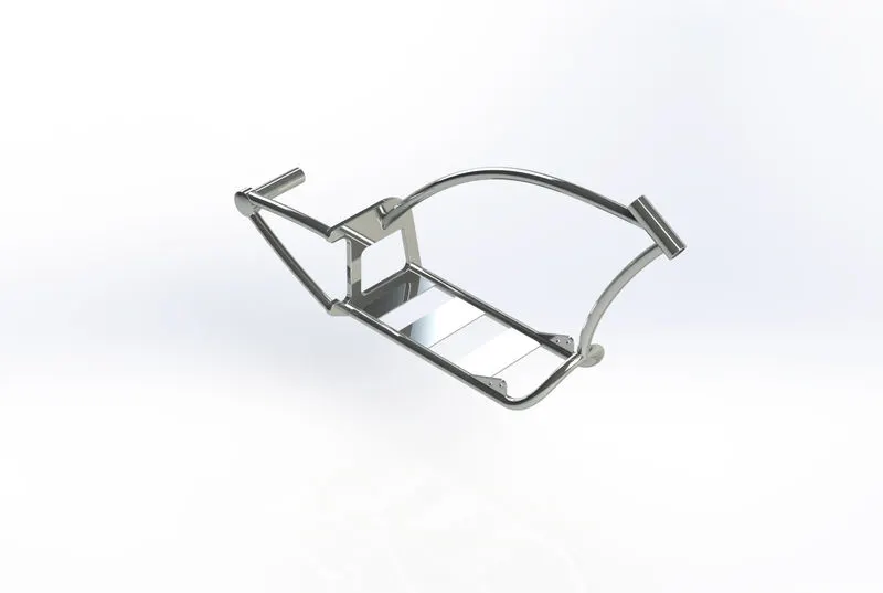
- Chassis
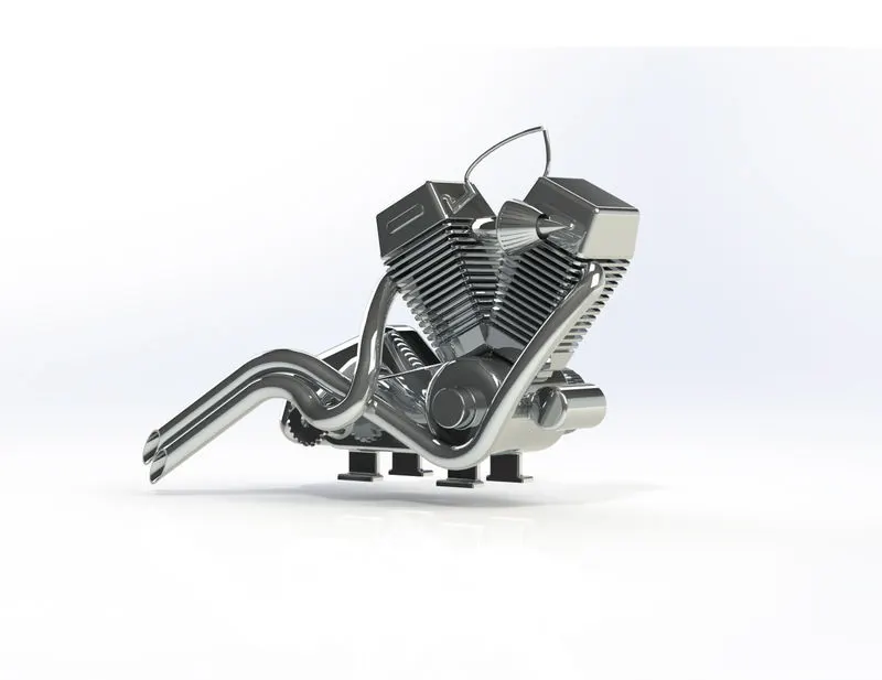
- Engine
In the designing of front fork most of the tools where used the projected line feature where mainly helped to create a product with better finish.
Engine is one of the most difficult part in the chopper all the main solid modeling tools are used in the process and with the help of projected lines the exhaust also created.
The tools which are used to make these parts are
- Sketch
- Convert entities
- Revolve
- Projected curve
- Dome
- Extrude
- Mirror
- Composite curve
- Sweep
- Circular pattern
- Split
- Fillet
SIXTH WEEK:
In the sixth week introduced new lessons about the surface modelling and solid modeling. The sixth week classes are mainly about the surface modelling different surface modelling tools where introduced. The part which is designed in the sixth week is
- Gas tank
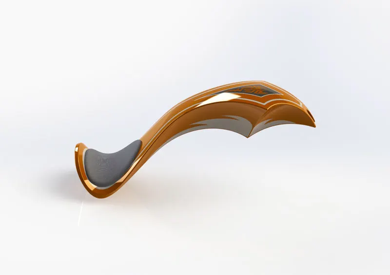
While designing of the gas tank both solid and surface modelling is used. Different surface modelling tools also used to create a better gas tank.
The main tools which are used other than the solid modelling tools are
- Lofted surface
- Swept surface
- Filled surface
- Surface trim
- Extended surface
- Surface knit
After creating all the parts the desired appearences also given to the material which will give a realistic effect when rendering the object.
SEVENTH WEEK:
in the seventh week after creating all the parts the assembly of the American chopper is carried out. By using different types of mates and others the assembly is done. Concentric, angle, distance, advance etc. these are the different mates that used. While doing the assembly some parts are again redesigned into our requirments. After completing the assembly process the feature called Decals also introduced which is really helped to enhance the look of the assembled American chopper.
RENDERING IN SOLIDWORKS
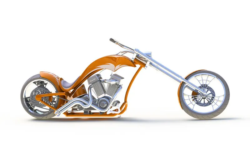
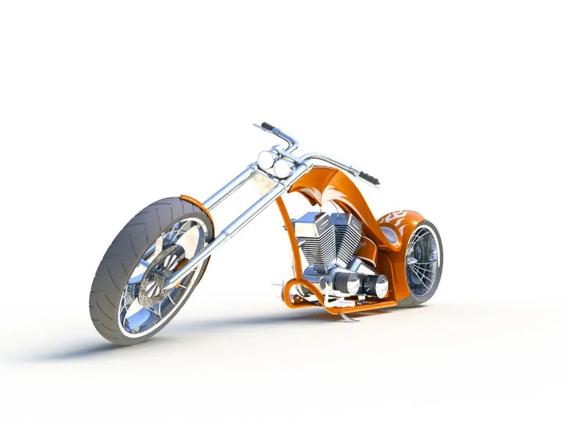
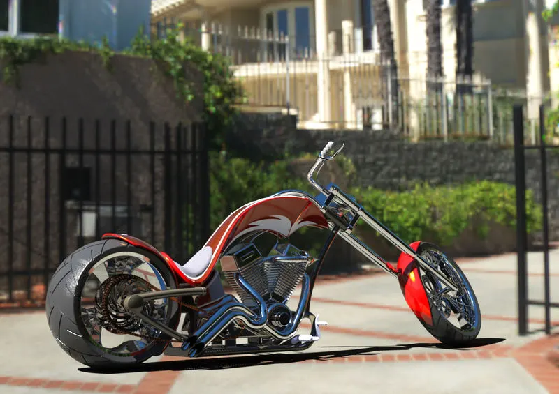
After the assembly we used the rendering tools in the solidworks with the help of photoview 360 . The rendering tools really helped to enhance the look of the American chopper . With the help of the product which have a real look is created.
SOLIDWORKS VISUALISE
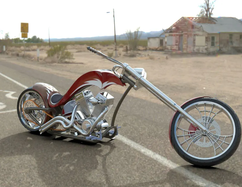
The solidworks visualise is a software that used only for the rendering purpose. It creates better outputs than rendering in the solidworks itself . It have a wide range of materials and realistic backgrounds and many different settings to create the rendering more realistic. Wide range of rendering options are available in this . with the help of solidworks visualise much more realistic images are created.
CONCLUSION
The assembly and rendering of the American chopper is successfully done by using solid works and solidworks visualize. From this I got good knowledge in solidworks tools and commands.