Week 9 - Attachment Feature Creation - Challenge 2
Aim: Creating the boss and Dog House for the Centre console coin holder considering the design rules.
Description:
THE GIVEN CLASS A-SURFACE IS NOT DRAFTED, SO IT CANNOT BE CLEARED IN EJECTION. WE NEED TO INFORM THIS ERROR TO THE TEAM WHICH HAS CREATED THE CLASS A-SURFACE.
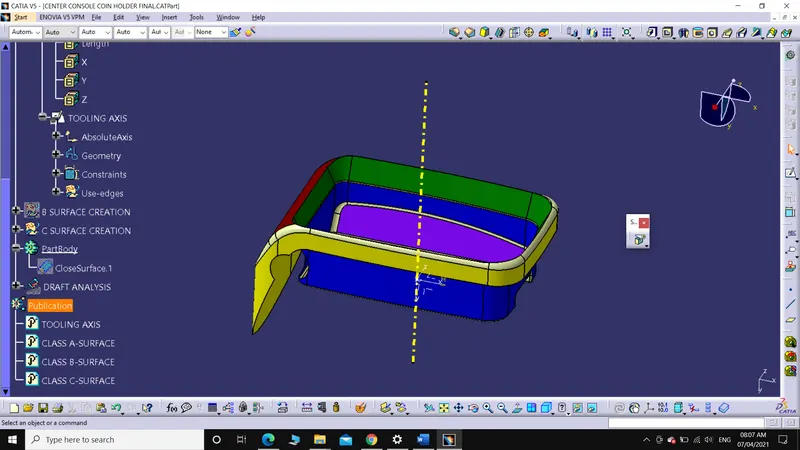
Steps involved in creation of tooling axis:
1. Extract the base surface and create a point on that, then insert axis system on the point.
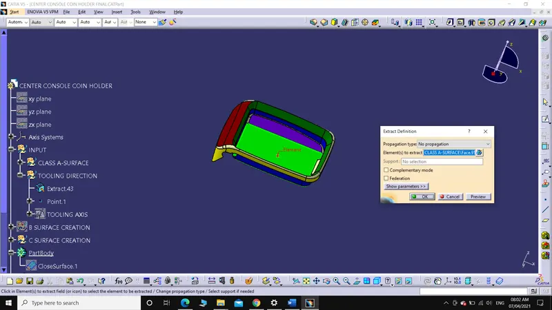
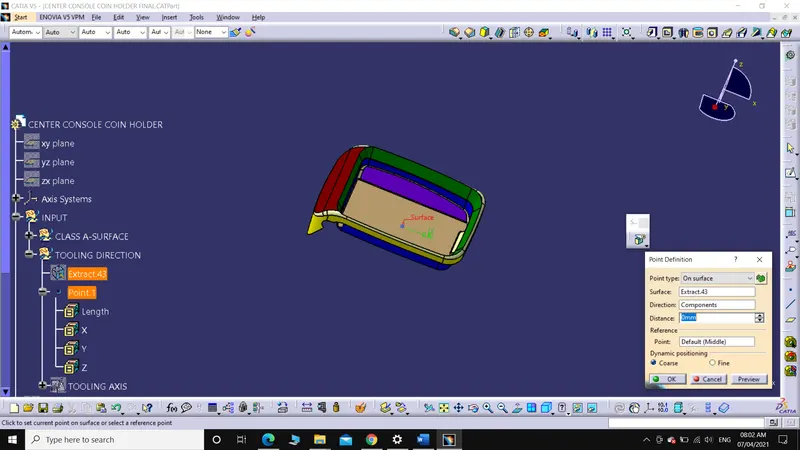
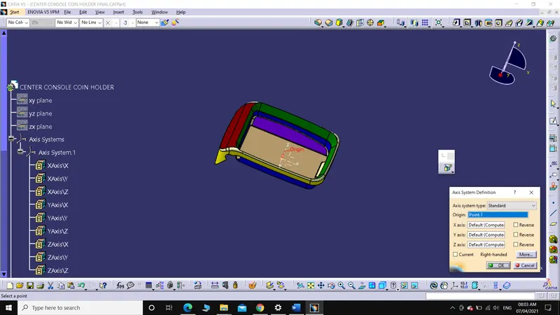
2. Using positioned sketch select the XY-Plane and enter the sketch mode. Now, use 3D intersect to trace the curve and then convert it to construction line.
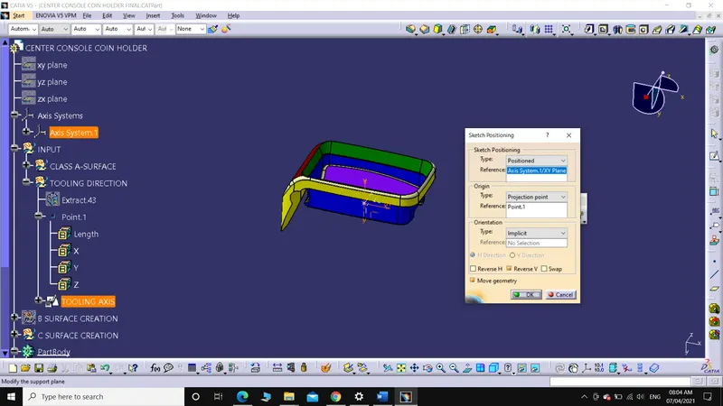
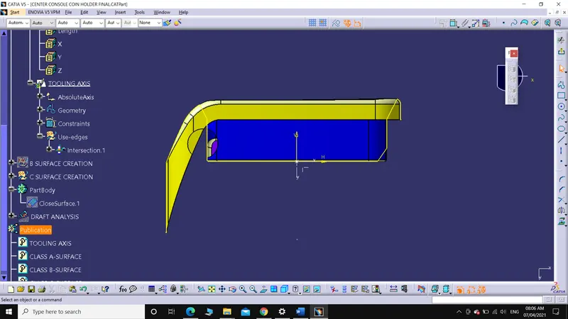
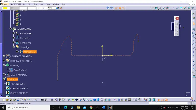
3. Draw two construction lines at the inclined curves and create a bisecting line using these two lines.
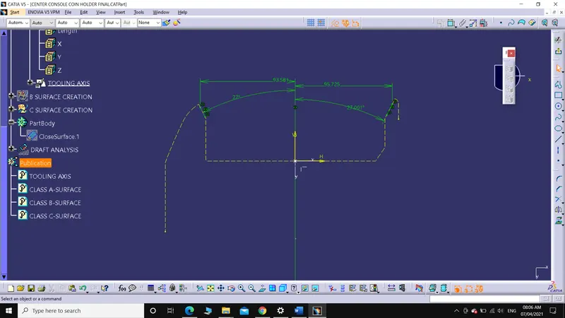
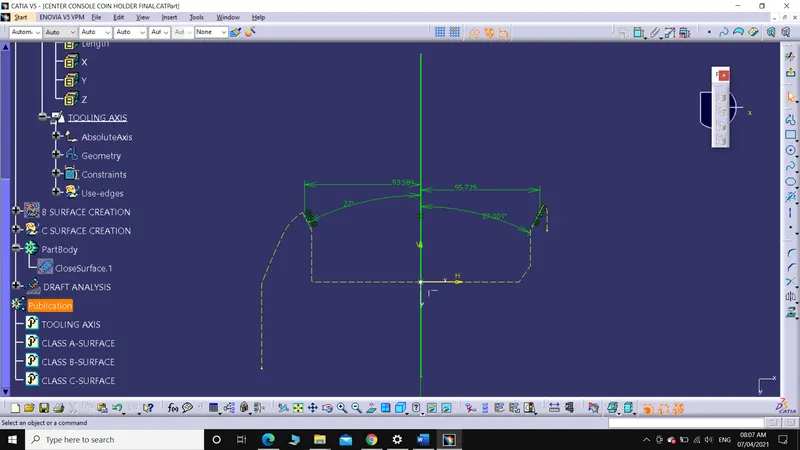
Steps involved in creation of Class B-SURFACE:
Creation of Base:
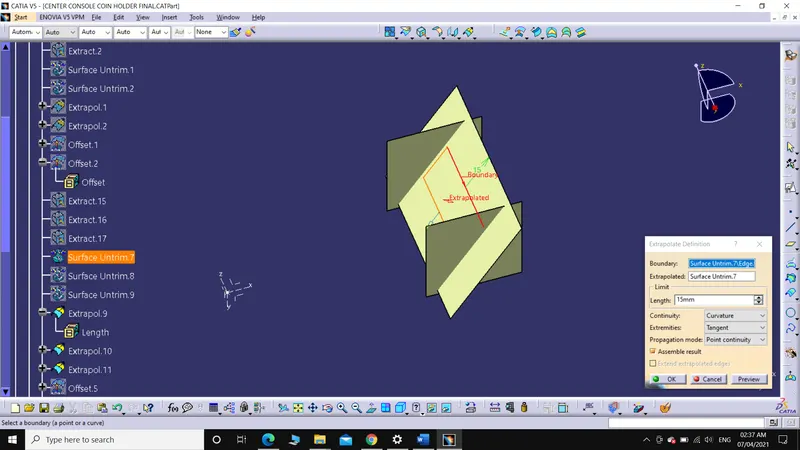
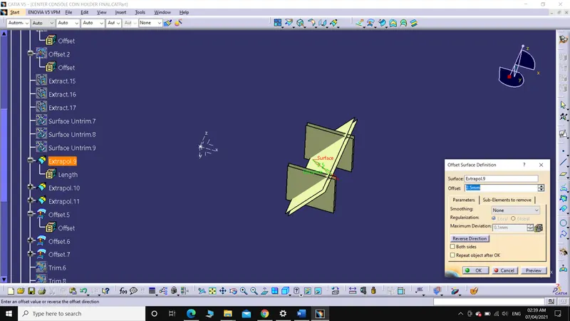
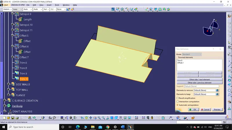
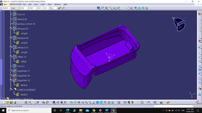
1. Extract the simple surfaces (which don’t have fillet), untrim surfaces.
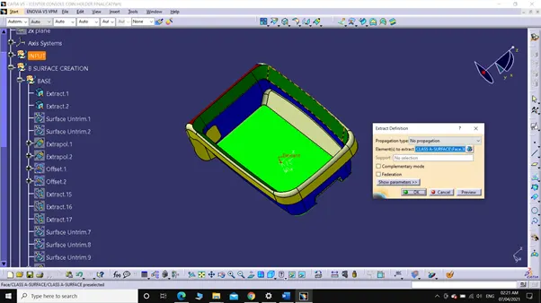
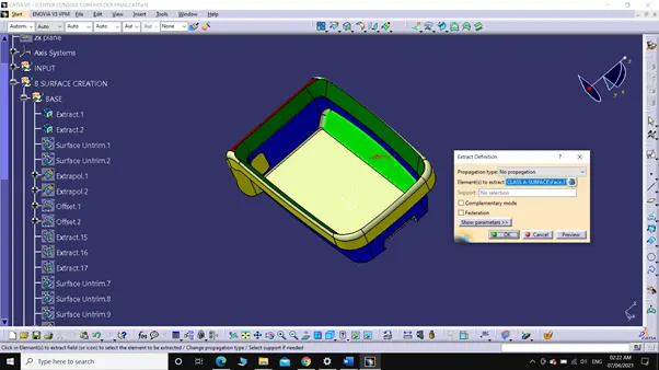
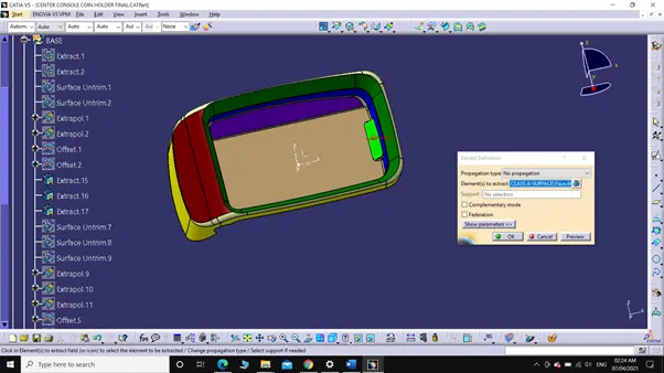
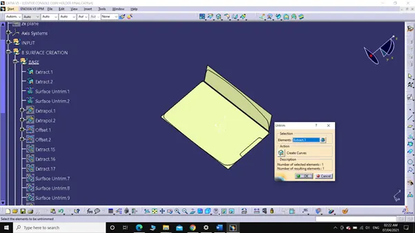
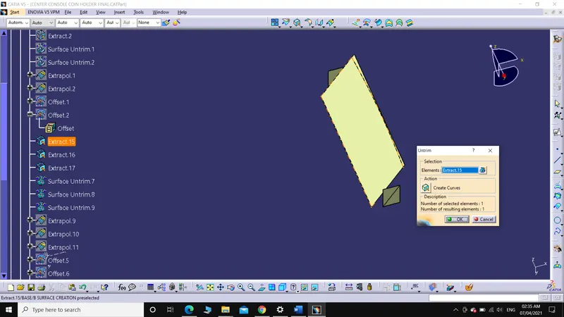
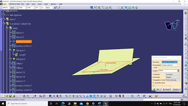
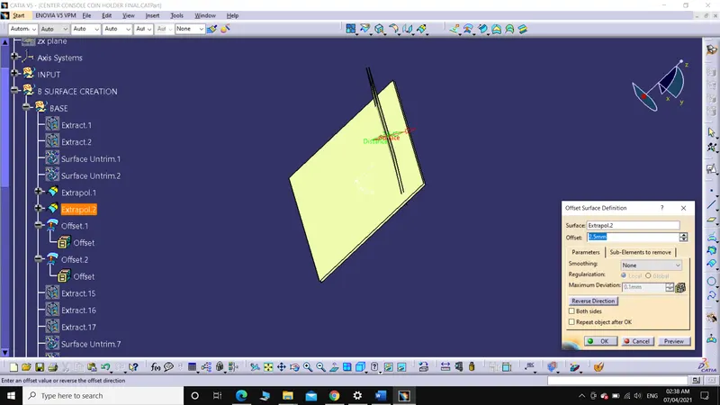
2. Extrapolate, offset and trim the surface to meet the required design..
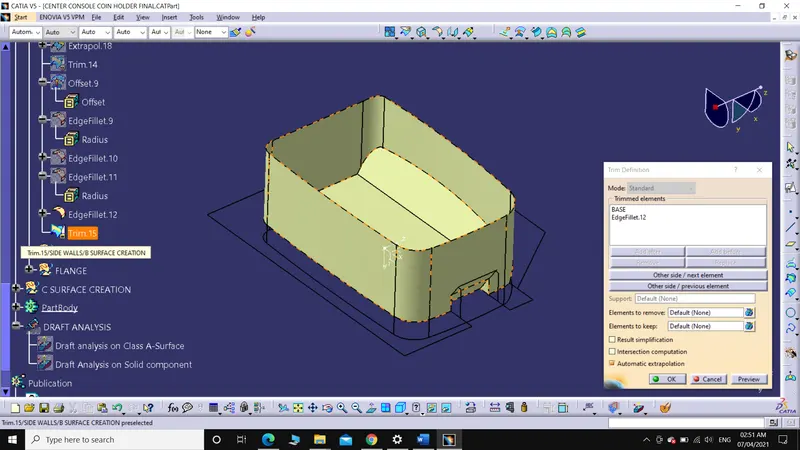
Creation of side walls:
1. Extract the simple surfaces (which don’t have fillet), untrim surfaces.
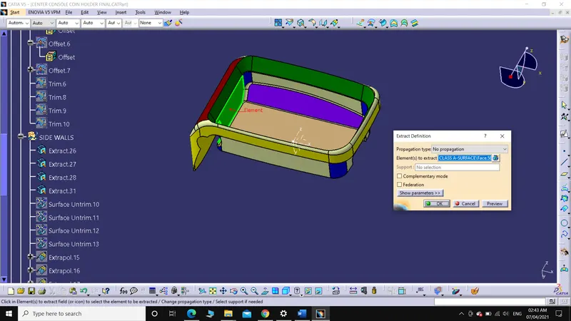
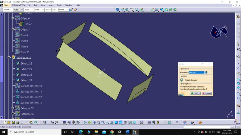
2. Extrapolate and trim the extra portion.
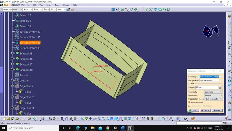
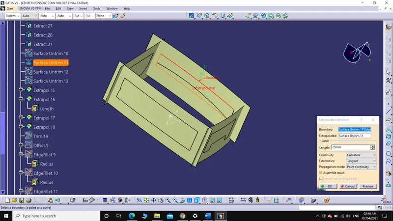
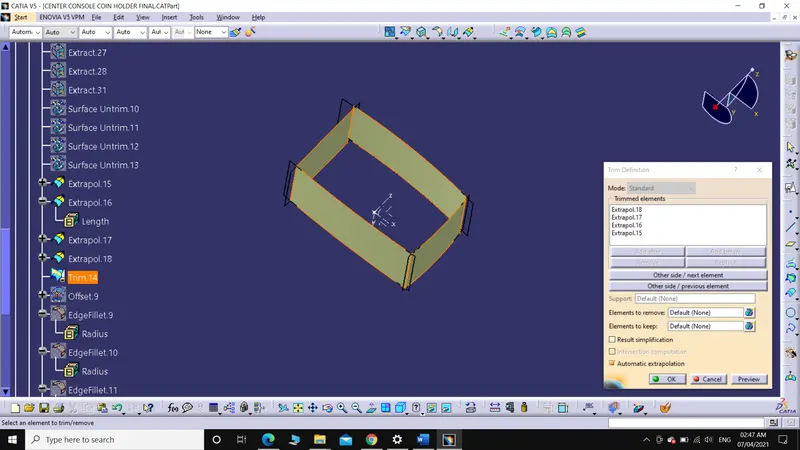
3. Offset the trimmed surface and offset it to distance of 2.5mm.
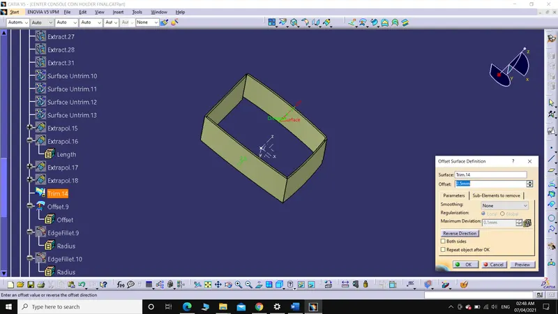
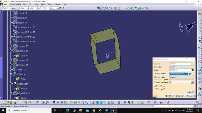
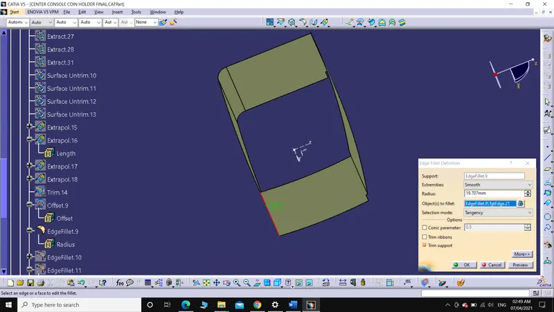
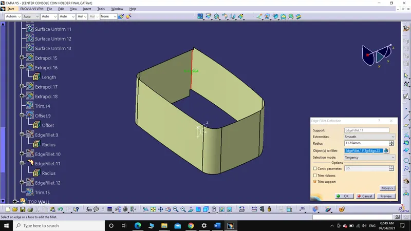
4. Trim the filleted surface with the base.
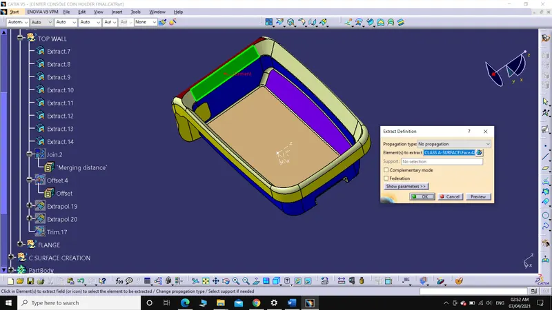
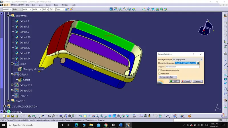
Creation of Top Walls:
1. Extract the top portion, join them using "JOIN" command and offset the same.
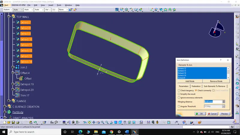
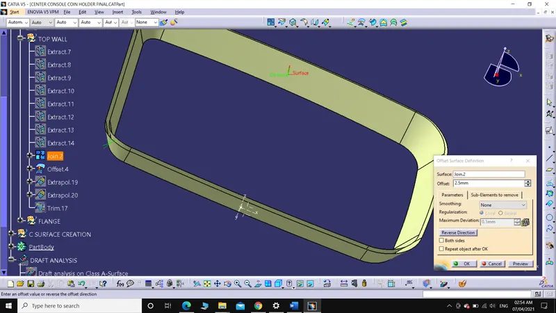
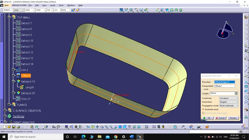
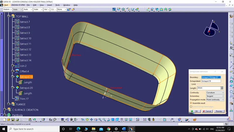
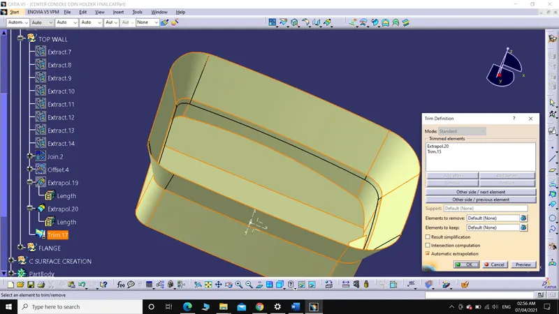
2. Extrapolate and trim with the side wall surface.
Creation of Flange:
1. Extract the surfaces, join them and offset at 2.5mm distance.
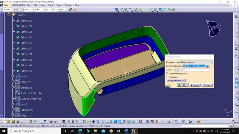
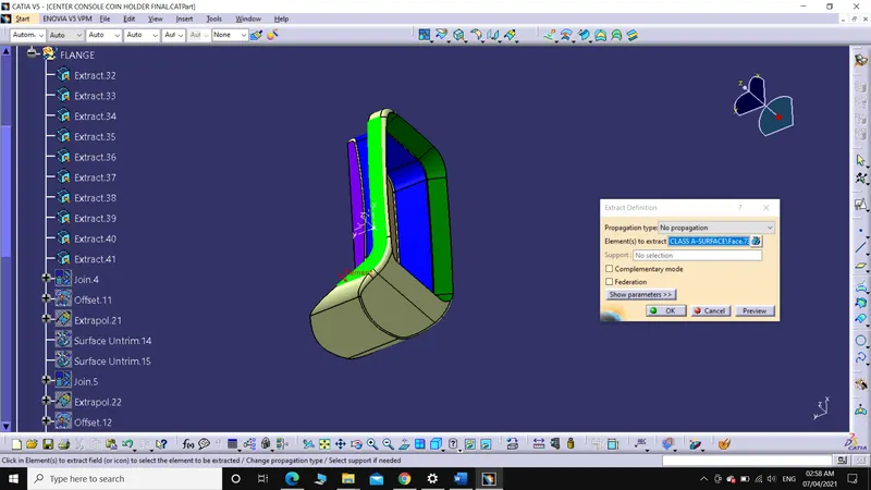
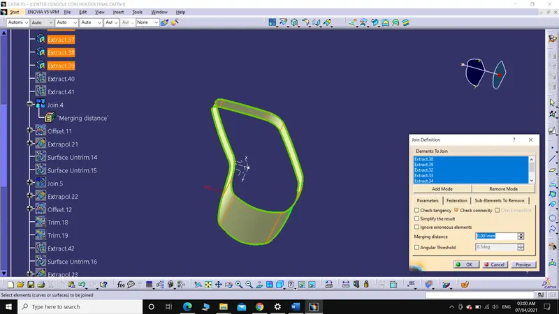
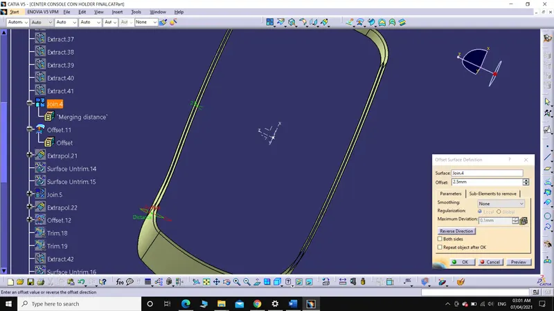
2. Extract the other part, since it can't be extrapolated, so just untrim the surface after extract.
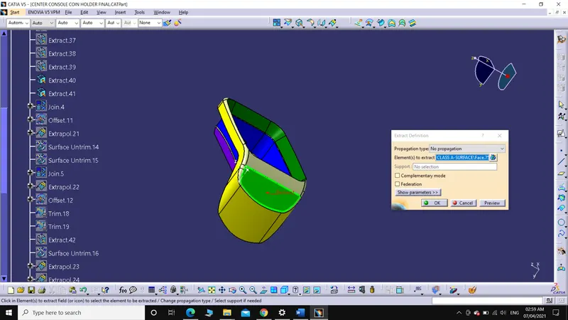
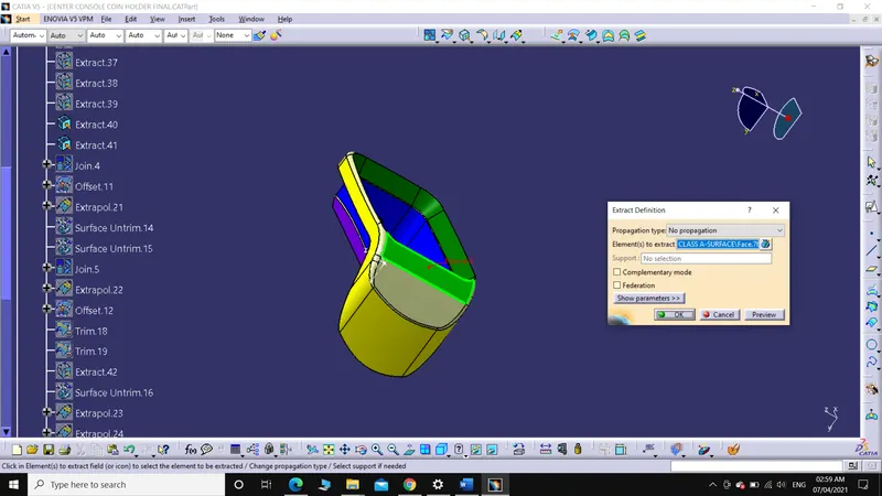
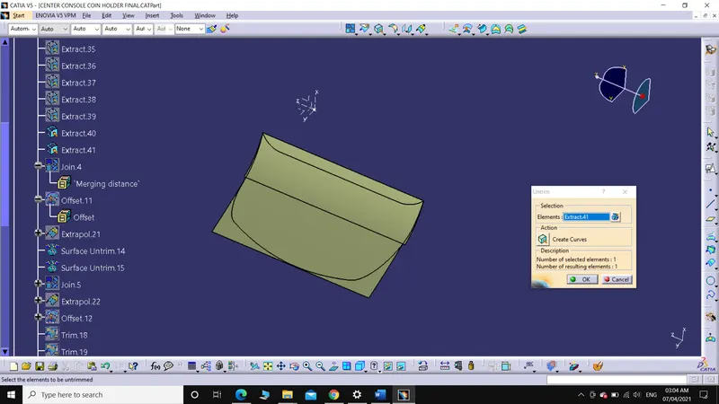
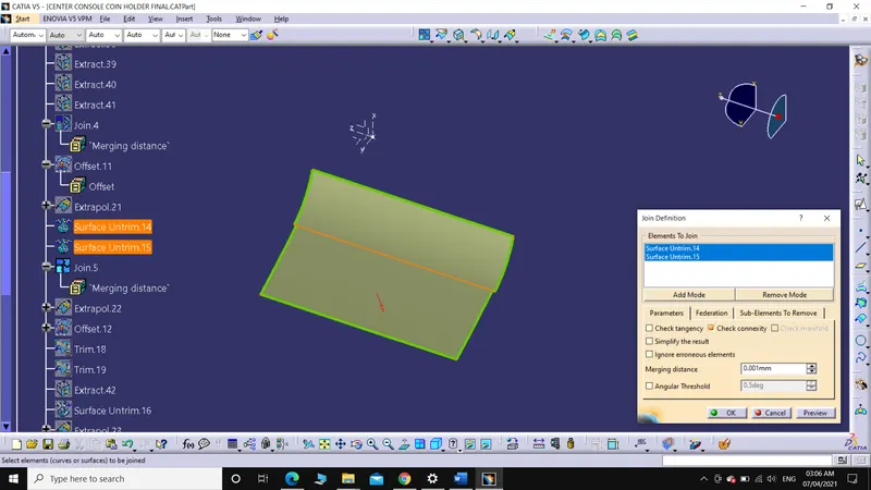
3. Join the surfaces, extrapolate, offset and trim as per requirement.
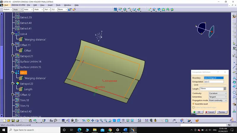
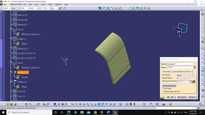
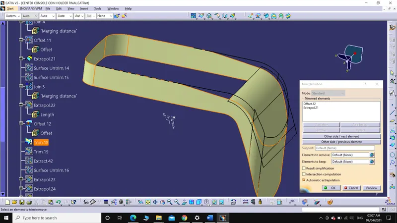
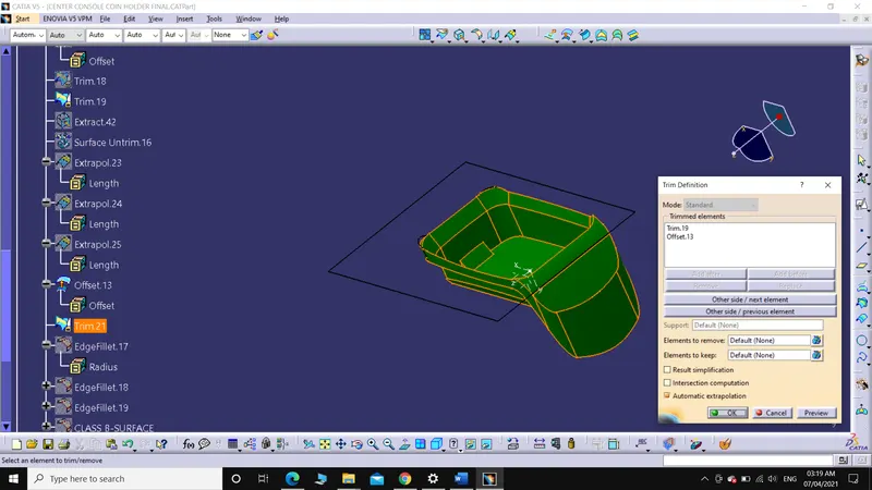
4. Trim flange with the top wall surface as shown below and fillets are applied on sharp edges.
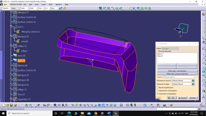
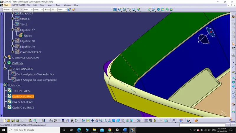
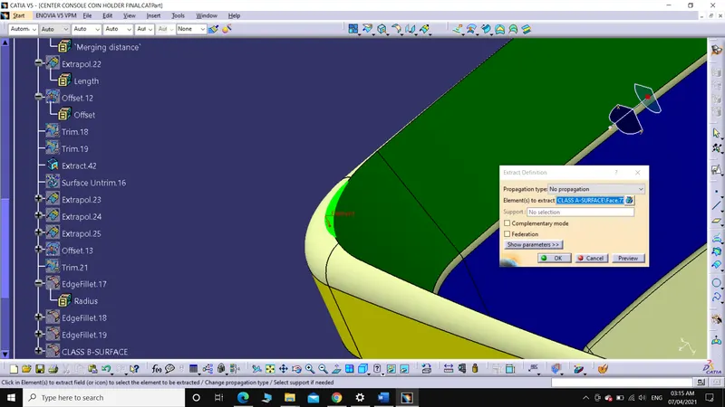
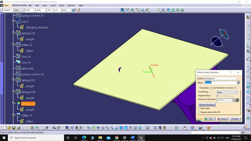
As we can see in the above picture that a part is not cleared in trim option. For which, we will
- Extract that part from Class A-Surface
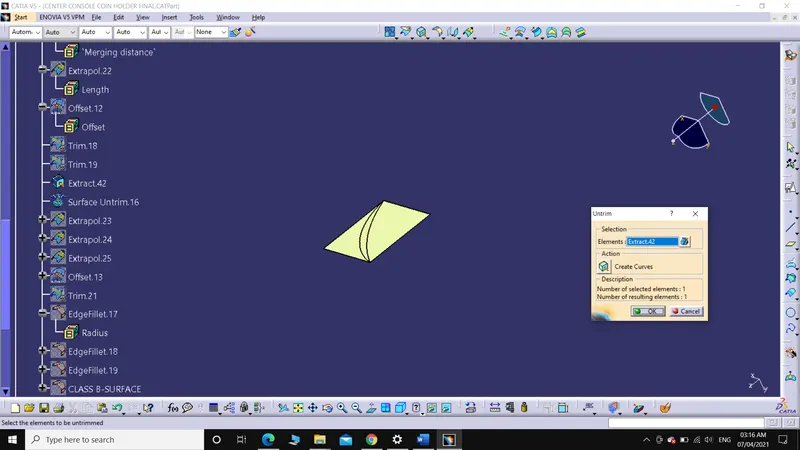
- Untrim it
- Extrapolate in all direction
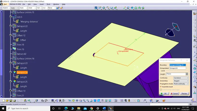
- Offset it to 2.5mm.
- Trim to get required surface
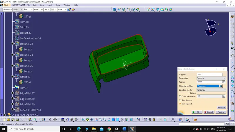
Fillets are applied at sharp edges
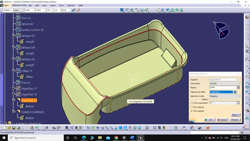
CLASS B-SURFACE.
Steps involved in creation of Class C-Surface:
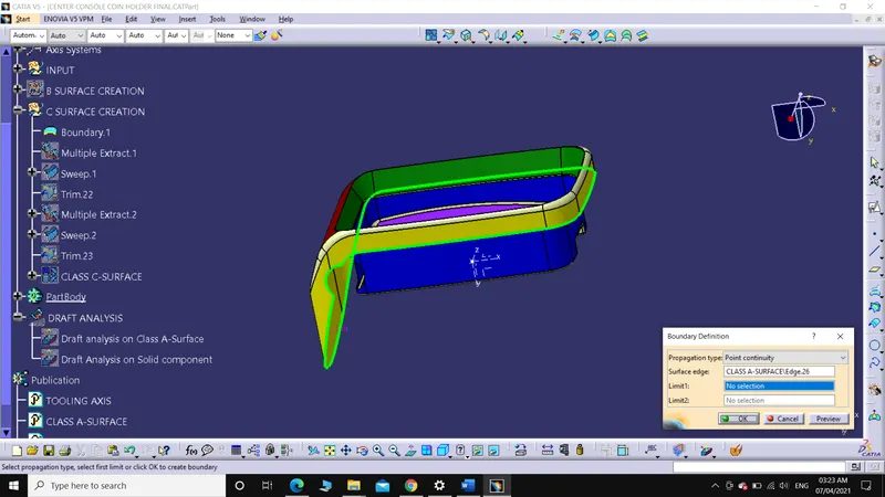
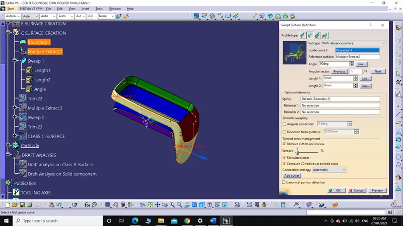
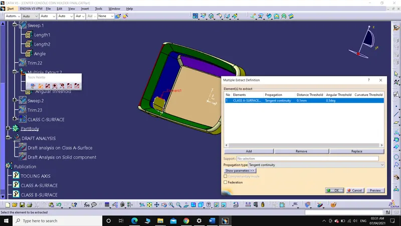
1. Extract the outer boundary and the adjacent surfaces to that boundary.
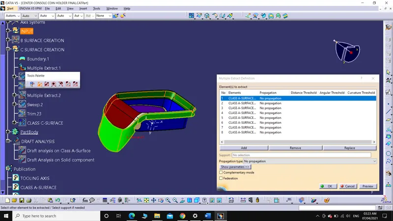
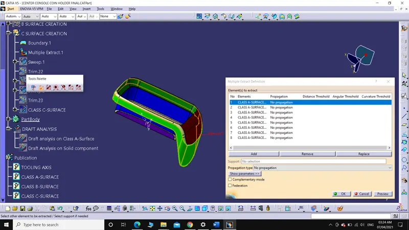
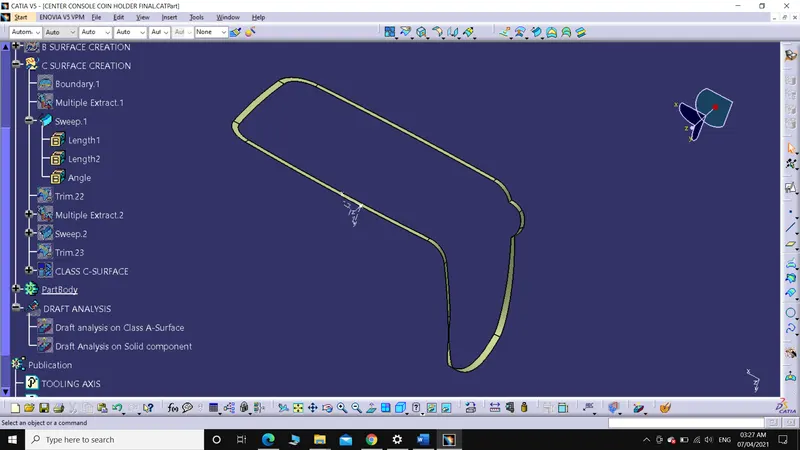
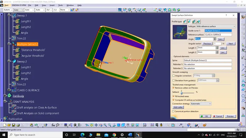
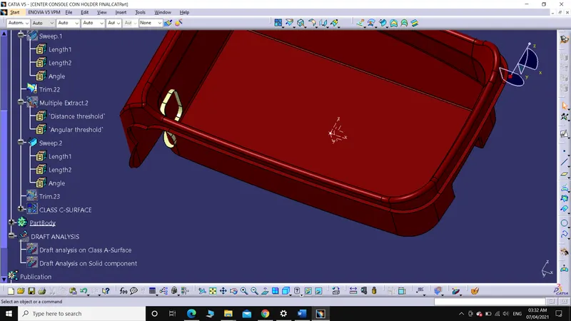
2. Using "sweep with reference surface" a surface at 90 degree has been created as shown in below pictures.
Where the outer boundary is profile and the extracted surface as reference surface.
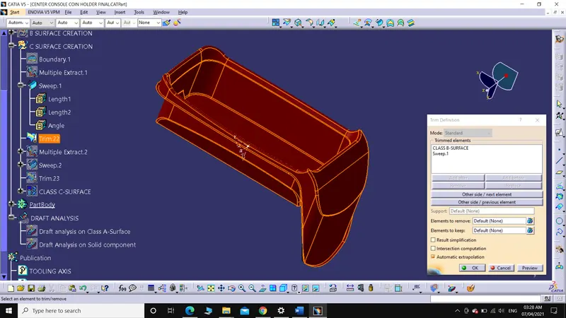
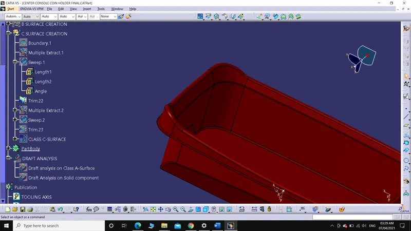
3. Trim the above sweep part with Class B-Surface.
4. Follow last two steps for hole and finally trim it with the lasttrimedsurface.

5. Finally, join the last trimmed surface with Class A-Surface and Class C-Surface is created.
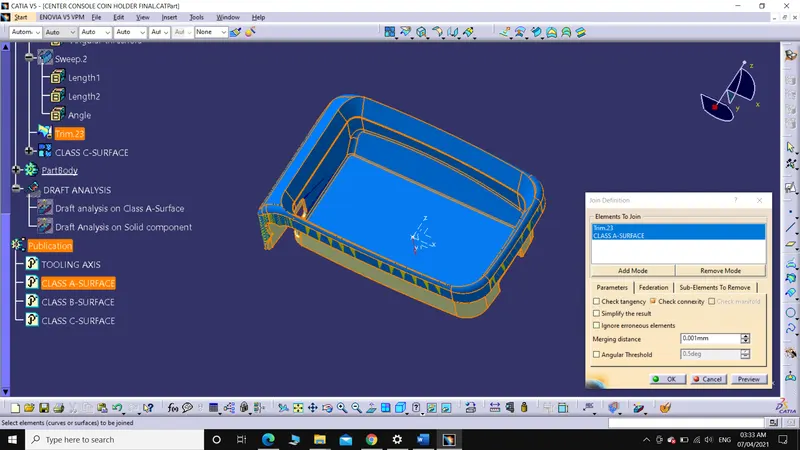
CLASS C-SURFACE.
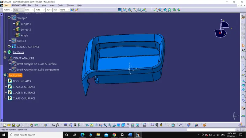
Steps involved in creation of Solid component:
1. Changing the window from "Generative shape design" to "Part design" and choose "Close Surface" from "Surface based features" toolbar.
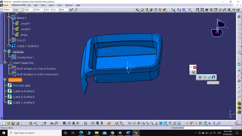
2. Selecting Class C-Surface as "Object to Close" and solid part is created.
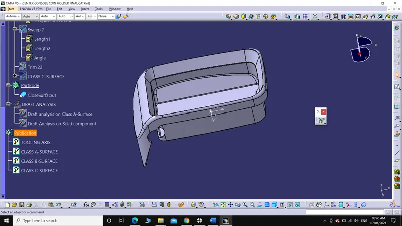
Screw Boss:
Screw boss is an engineering feature which is usually at the B-side surface, the main objective of screw boss is to aid the assembly of components by providing a channel for screw.
Guidelines for Screw Boss Design:
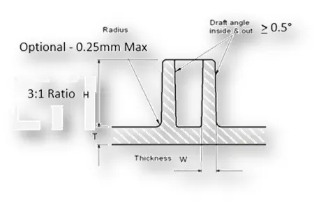
Numerical values considered for designing Screw boss:
T = 2.5mm
d = 4mm (Dia. of minor circle)
X = 0.6*2.5 = 1.5mm
Major circle = (60% of T) + (Radius of minor circle).
R = 0.25mm
We have a relation between Diameter of major circle and Height of the Screw base,
H/D `<=` 3
H `<=`18mm
Numerical values used in the rib design around screw boss by following the design rule.
⦁ Thickness(t) = 2.5mm
⦁ Rib draft = 0.5 degrees (because it is the min value)
⦁ Rib fillet radius(r) = 0.25mm
⦁ Rib root thickness should be > 30% of Thickness
⦁ Rib thickness(w) = 0.4*2.5 = 1mm
⦁ Rib depth = 5*2.5 = 12.5mm (considering the min value)
Steps involved in Screw Boss creation:
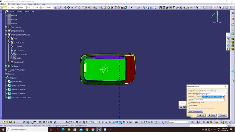
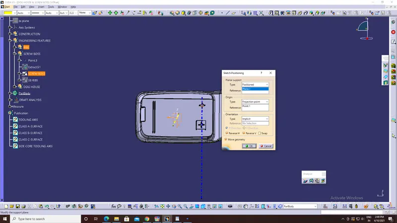
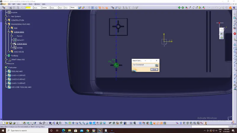
1. Extracting the class A-Surfaces' bottompart.Creating a point on the surface, enter the sketch part and draw the required sketch and using above dimensions.
Major circle = (60% of T) + (Radius of minor circle).
2. Creating a new part body and pad the screw boss sketch to a length of 20mm.
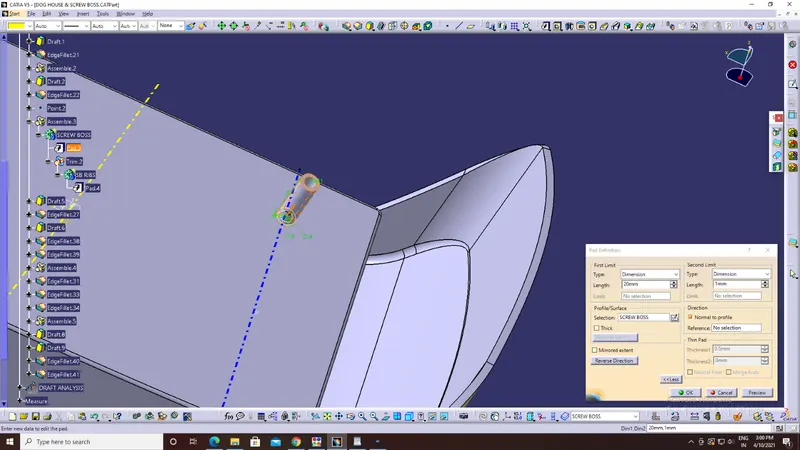
For better strength of the screw boss, rib support is required for boss. Again, enter the define the positioning sketch and draw the profile for the ribs. Pad the rib profile for a length of 12.5mm.
*Note: Guideline of Rib design are followed while creating ribs around the Screw Boss.
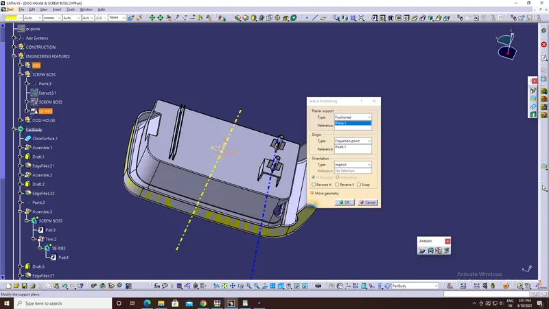
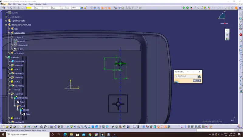
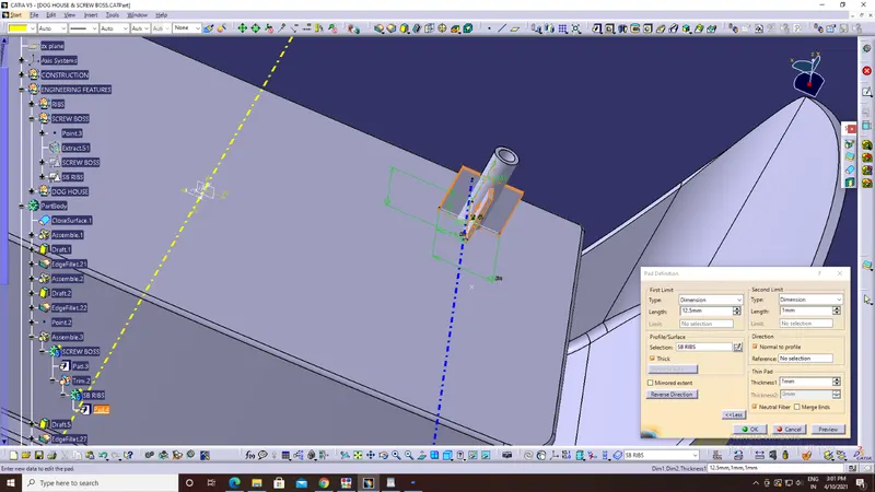
The ribs created around the screw boss tend to intersect through the screw boss. So, using Union trim option we clear the portion intersecting the screw boss.
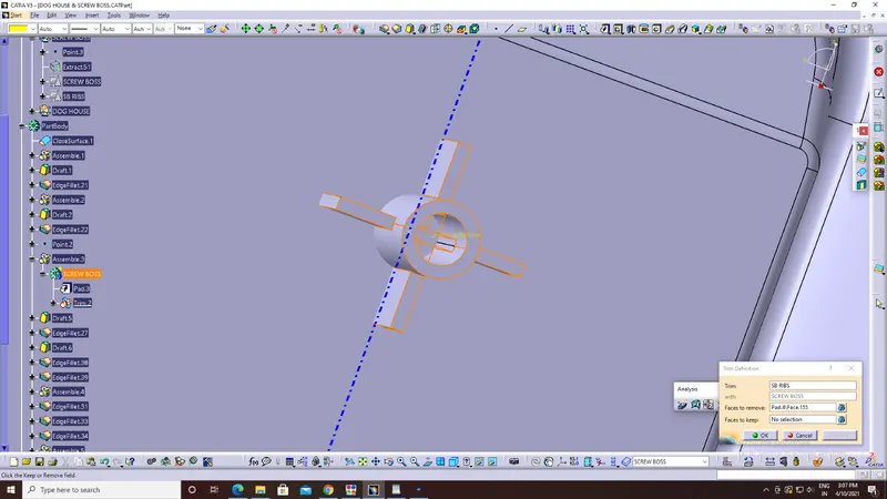
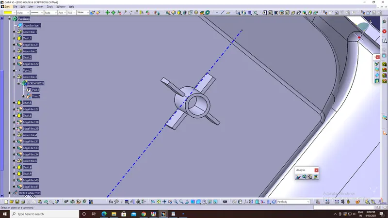
Finally, using assemble Boolean operation assemble it to main part body.
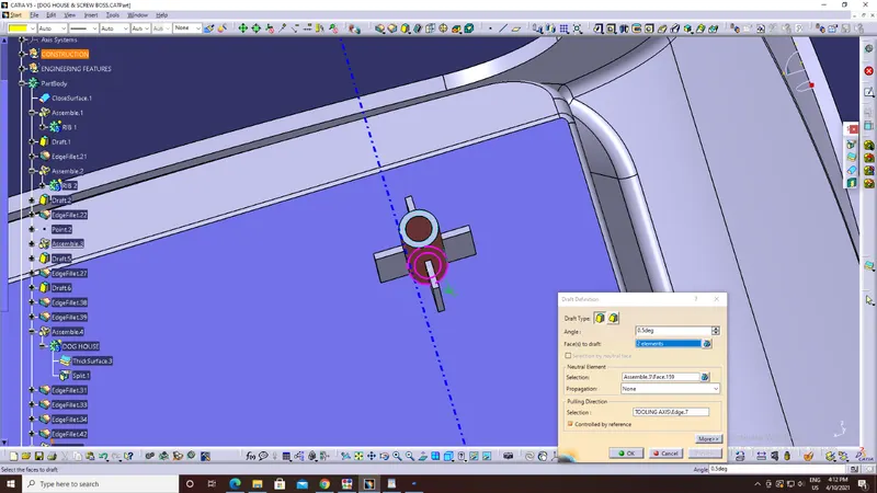
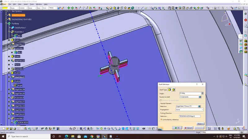
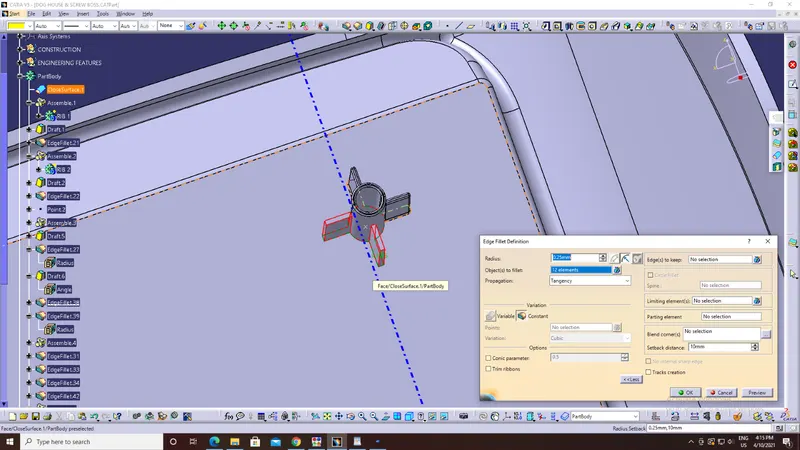
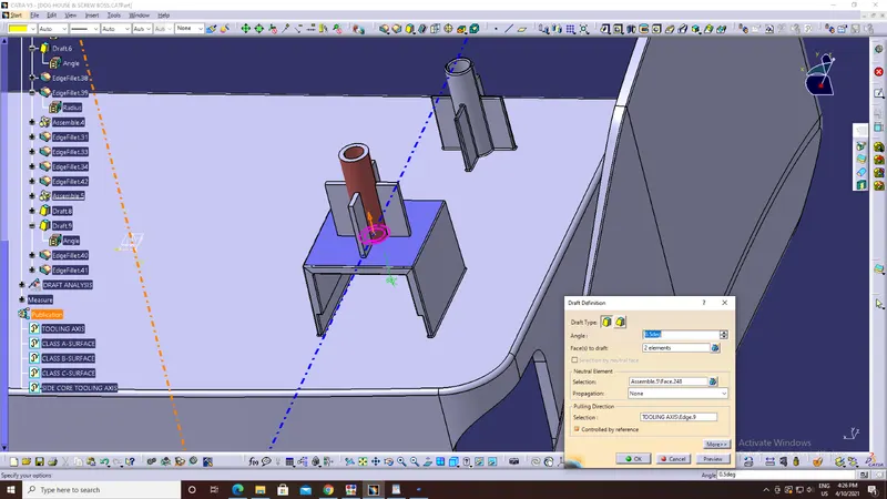
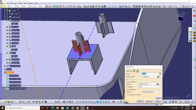
3. Provide draft of 0.5 degrees both inside and outside face of Screw boss and for the ribs with the bottom surface of the coin holder as neutral surface. And fillet the sharp edges.
Dog House creation:
Dog House: It is an engineering feature that is present at the B-side of the surface and this helps in,
- Prevents Sink marks on the surface.
- Helps other engineering features for placing them at some elevation.
- If any engineering features needs to be attached in perpendicular direction Dog house is used.
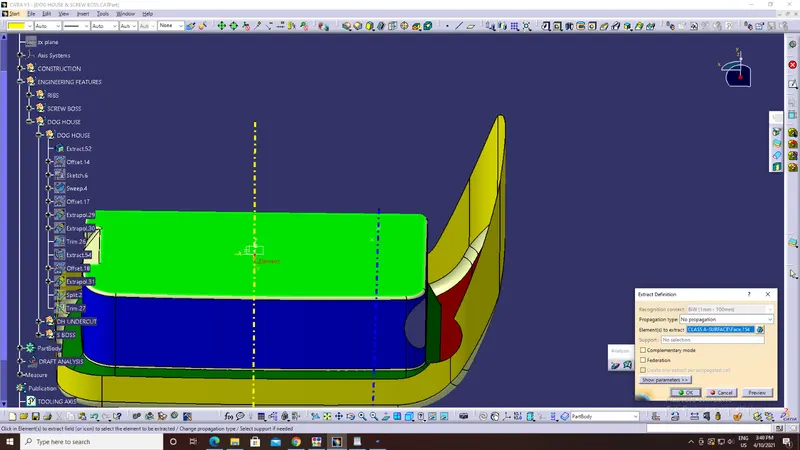
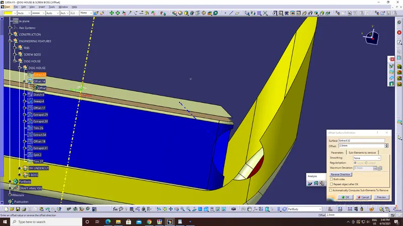
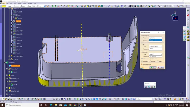
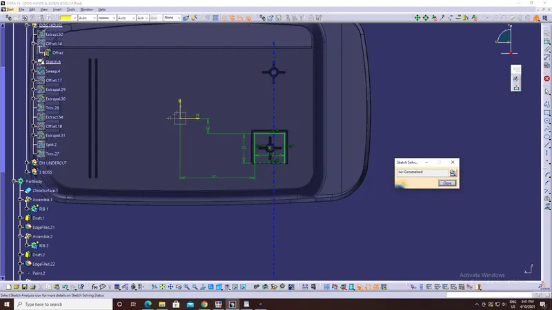
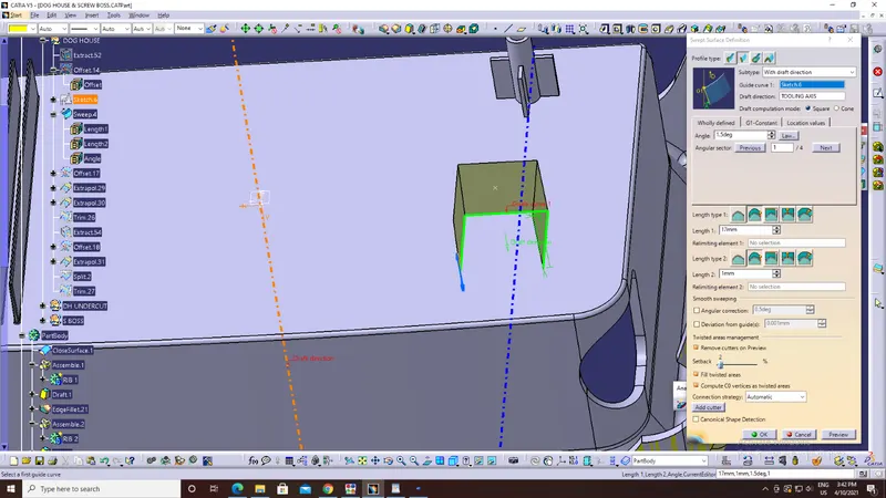
1. Extract the bottom surface of the Coin holder or extract from Class A-Surface and offset it to 2.5mm. Define a positioning sketch and create a profile for the dog house and sweep this profile along tooling axis (with angle 1.5degrees) orExtrude the profile and provide draft of 1.5 degrees.
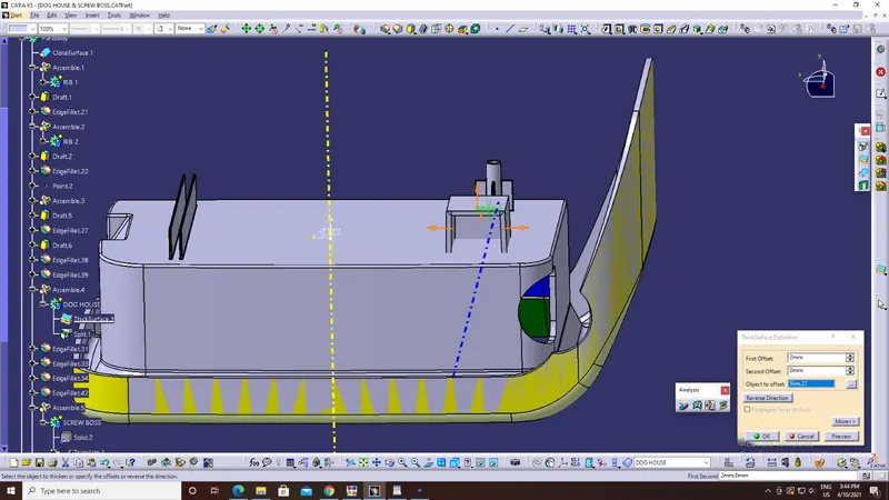
2. Changing window to part design and give thickness to Dog house surface body of 2mm.
3. There is an under cut at bottom of the Dog House an there are certain rules to be followed,
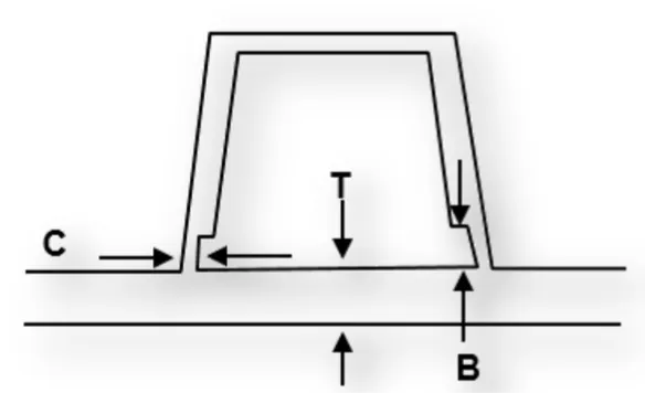
Doghouse wall thickness at the intersection of the part wall (C) should be 40% or less than the main wall thickness (T).
Height (B) should be between 3.0 – 6.0mm
Considered value for design:
T = 2.5mm
C = 0.4*2.5 = 1.5mm
B = 5.0 mm
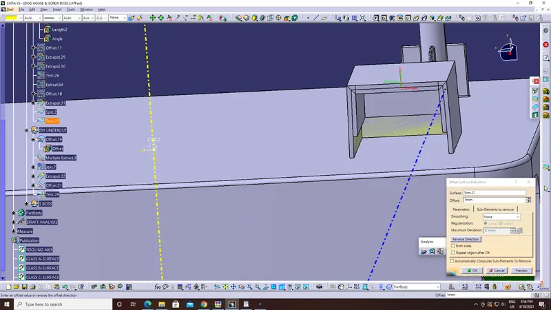
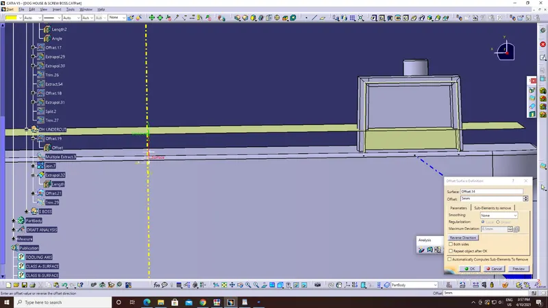
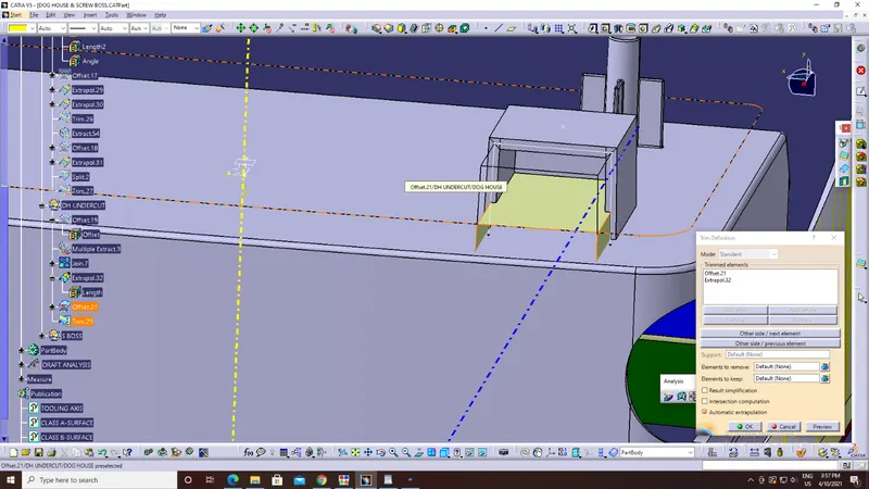
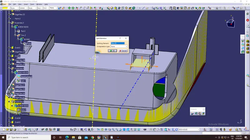
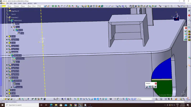
The under-cut at the bottom of the Doghouse can be done by creating a surface of required dimensions and splitting it form the Dog house solid body.
(The surface body for under-cut can be done by just offsetting and trimming the surfaces.)
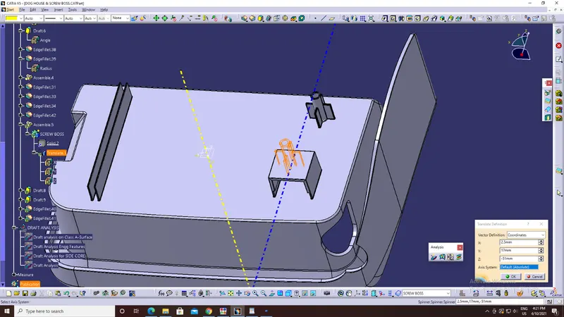
4. The screw boss which was created previously is copied and pasted using ‘paste special option’ where ‘As result with link is used’ and then is translated onto the Doghouse and Assembled using Assemble Boolean operation.
Finally draft the screw boss and ribs around it after assembling (adding it to the main part body).
Side core Tooling axis:
The outer faces of Doghouse created can be easily cleared along tooling axis but the inner face can only be cleared along other axis which we can say ‘side core axes. This can be created by using bisecting line option.
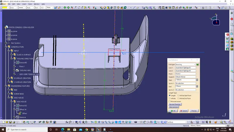
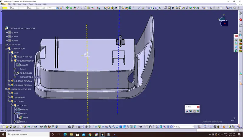
Provided draft of 0.5 degrees for the inner face of under-cut along Side-core tooling axis.
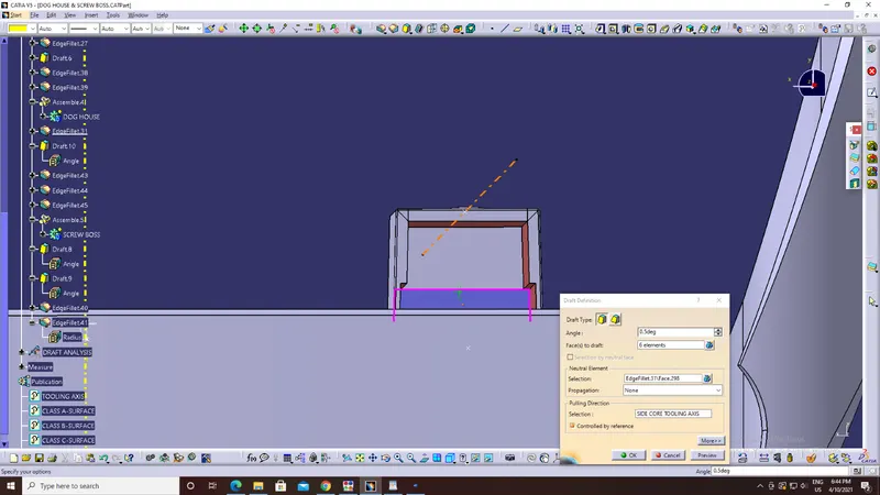
5. Fillet all the sharp Edges of the Doghouse and screw boss which is on the Doghouse. Since the wall thickness at the bottom of doghouse is 1mm we cannot apply the fillet rule (Outer fillet = Fillet radius + Thickness), So just provide the min radius value i.e., R = 2.5mm.
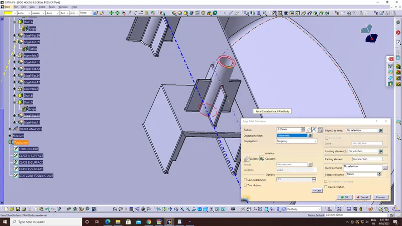
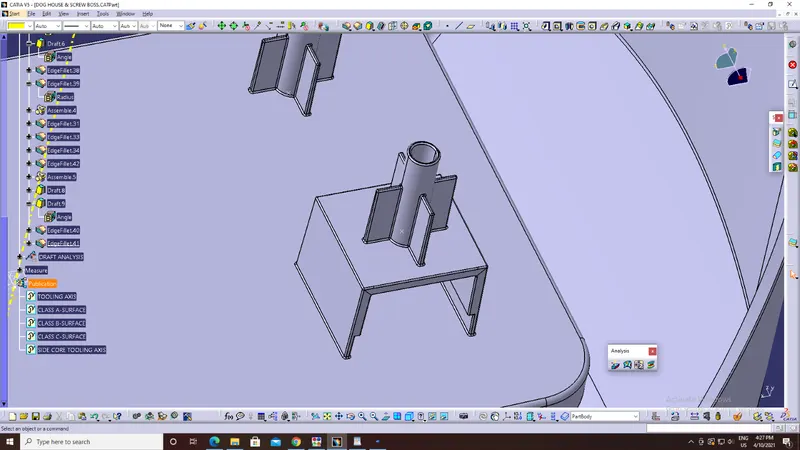
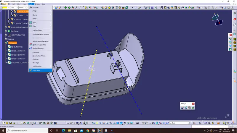
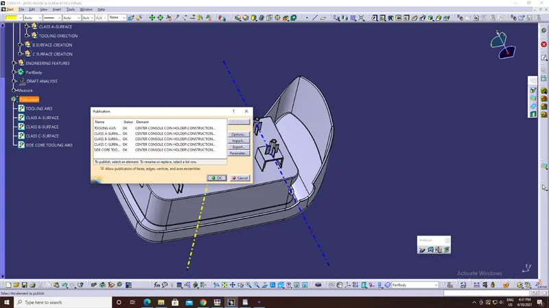
Class A, B, C and tooling axes are published so that it can be selected quickly for particular operations:
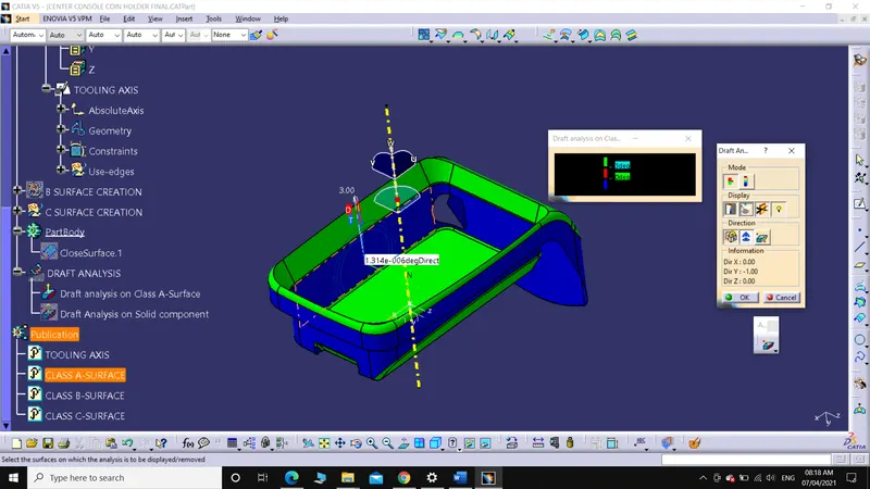
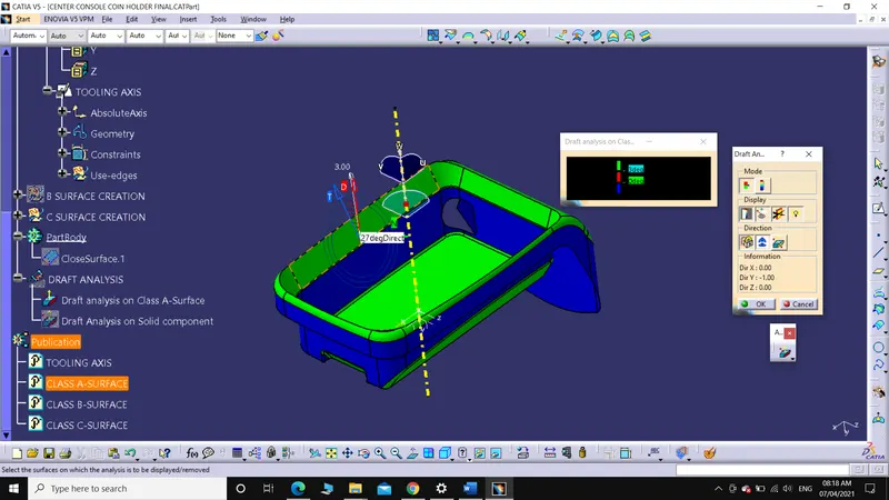
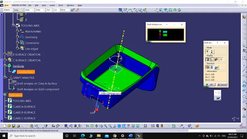
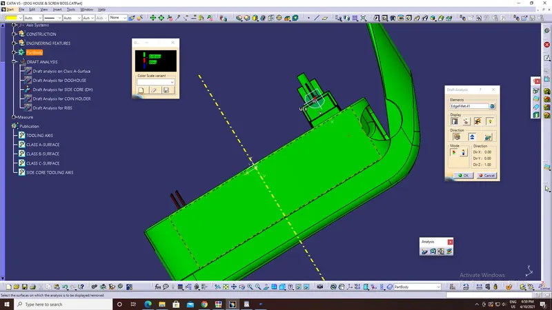
Steps involved in Draft analysis on Class A-Surface of Coin holder:
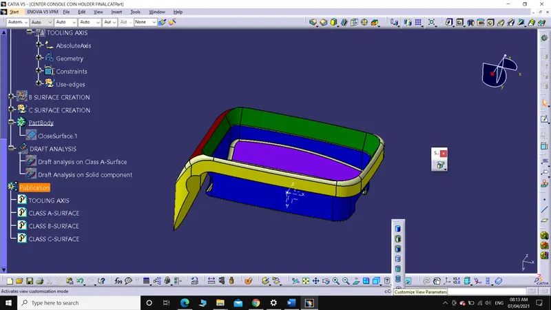
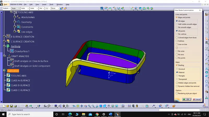
1. Select 'Customize view parameters' from the 'View mode' and choose 'Materials'.
2. Select 'Feature Draft Analysis' from the 'Analysis toolbar'.
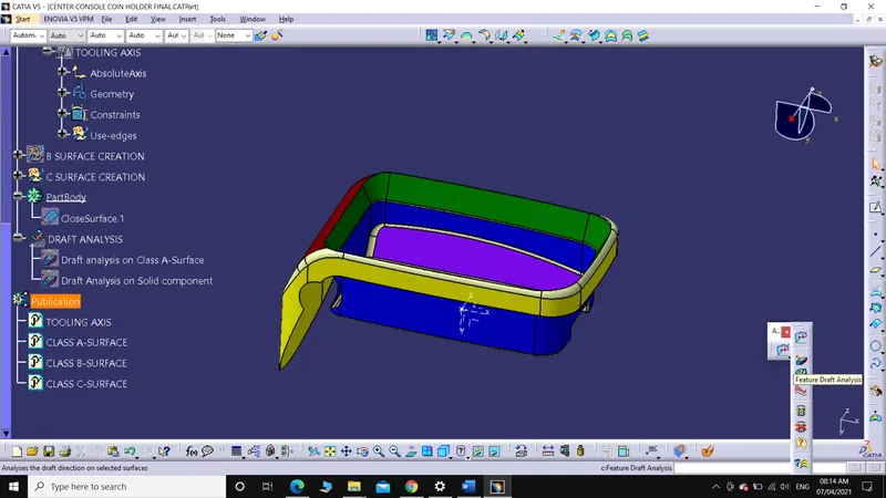
3. Now, holding the red-dot, which is on the compass (present on Top-right corner of the window) align with the Tooling axis and lock it.
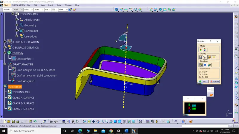
4. Set the Minimum draft angle (3 degree for plastic components) in 'Draft Analysis' dialog box (Which has differentcolorbars).
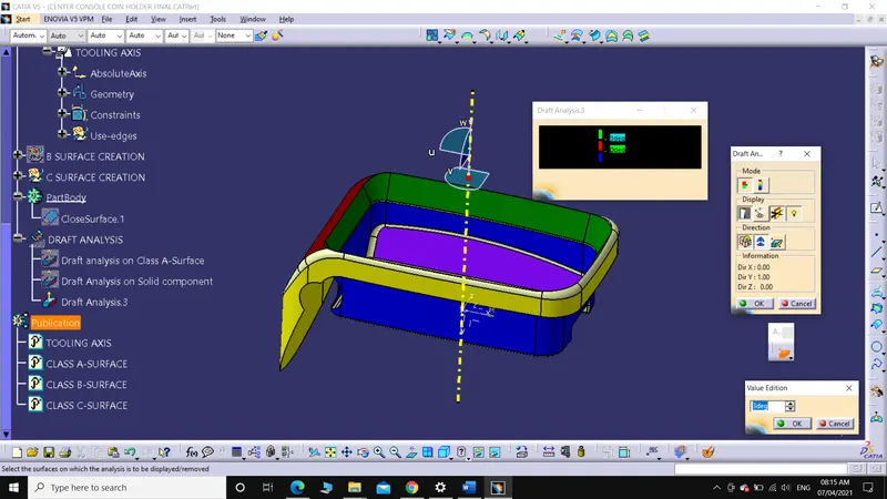
5. Choose Class A-Surface of Coin holder as element in 'Draft Analysis' dialog box or Just click on the surface.
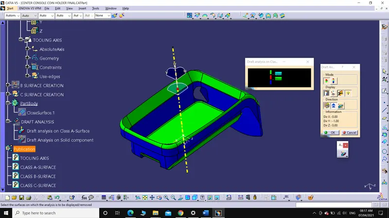
6. After selecting if the colour changes to,
Green, then the draft of the Part has minimum draft angle of 3 degree.
Red, then the draft angle of the part lies between 0-3 degree.
Blue, then the draft angle of the part is less than 0 degree.
7. By choosing 'Analyse under running point' from 'Analysis toolbar' we can check the draft angle at any point on the surface just by moving the pin.
Steps involved in Draft analysis on,
- SOLID COIN HOLDER COMPONENT:
1. Select 'Customize view parameters' from the 'View mode' and choose 'Materials'.
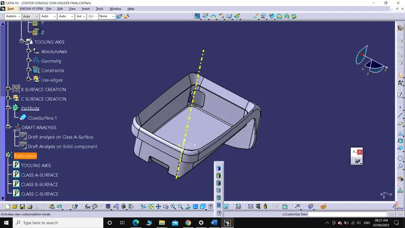
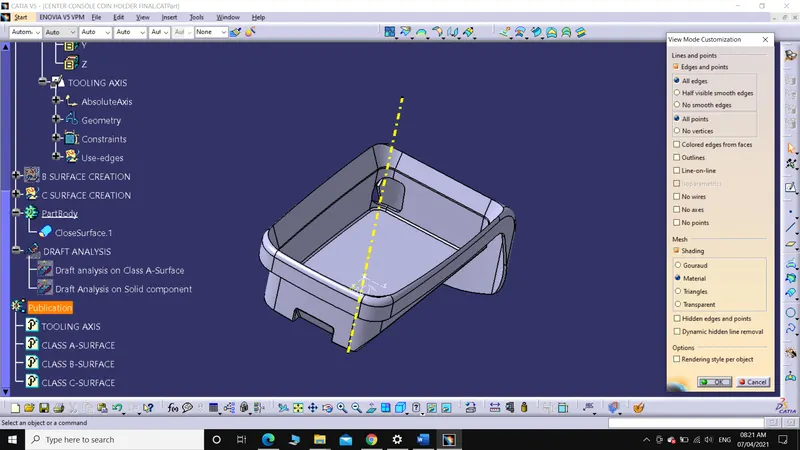
2. Select 'Feature Draft Analysis' from the 'Analysis toolbar'.
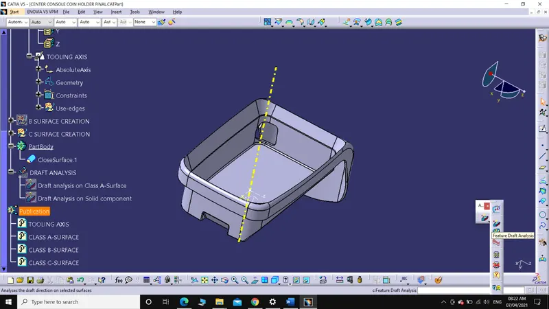
3. Now, holding the red-dot, which is on the compass (present on Top-right corner of the window) align with the Tooling axis and lock it.
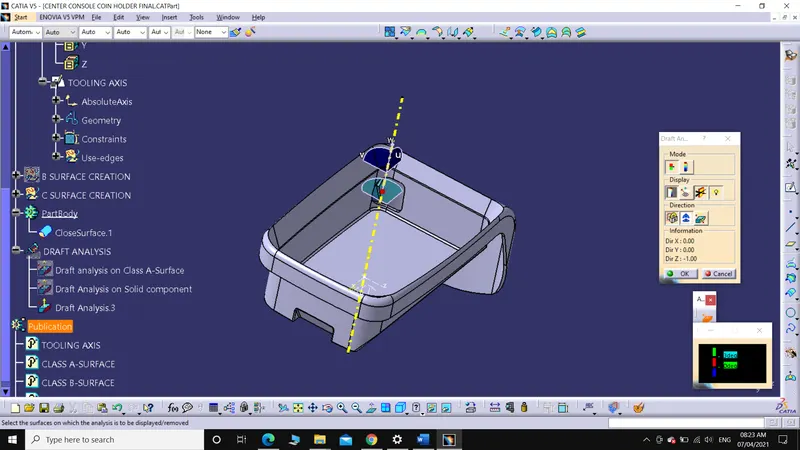
4. Set the Minimum draft angle (3 degree for plastic components) in 'Draft Analysis' dialog box (which has differentcolourbars).
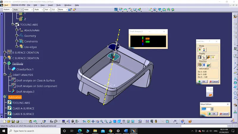
5. Choose Solid component as element in 'Draft Analysis' dialog box or Just click on the surface.
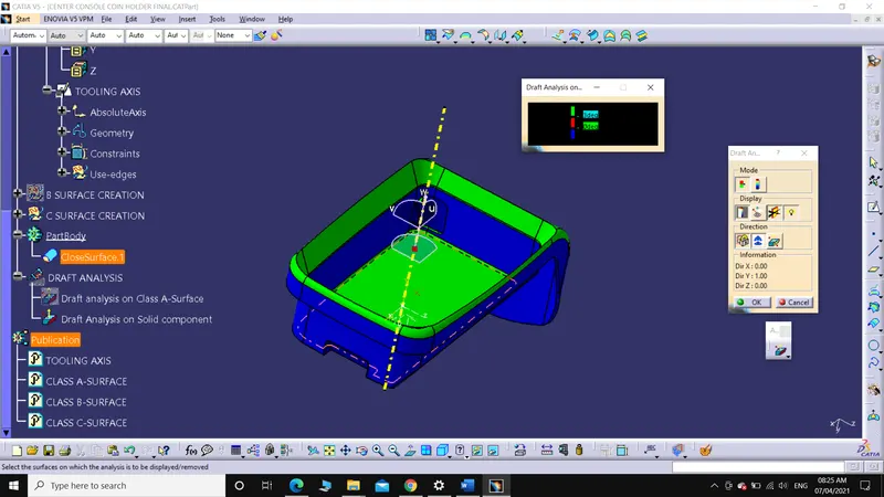
6. After selecting if thecolourchanges to,
Green, then the draft of the Part has minimum draft angle of 3 degree.
Red, then the draft angle of the part lies between 0-3 degree.
Blue, then the draft angle of the part is less than 0 degree.
7. By choosing 'Analyse under running point' from 'Analysis toolbar' we can check the draft angle at any point on the surface just by moving the pin.
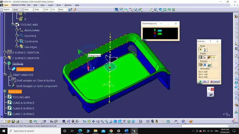
- RIBS (Individual and ribs surrounding screw boss)
Follow above steps only changes will be,
The minimum draft angle which is 0.5 degrees (but I have considered 0.45 degrees with `+-`0.05 degrees tolerance).
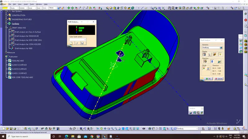
- DOGHOUSE:
a. Along Tooling axis:
Follow above steps only changes will be,
The minimum draft angle which is 1.5 degrees (but I have considered 1.45 degrees with `+-`0.05 degrees tolerance).
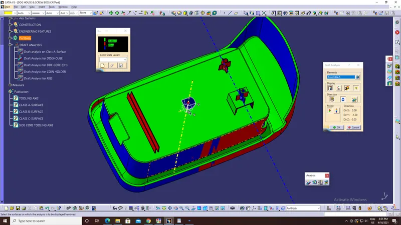
b. Along Side core axis:
Follow same steps but side core axis is considered for placing compass.
The minimum draft angle which is 0.5 degrees (but I have considered 0.45 degrees with `+-`0.05 degrees tolerance).
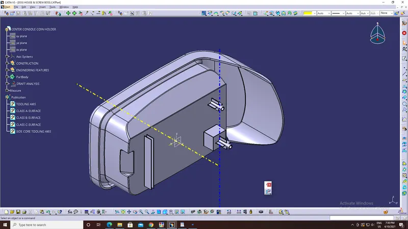
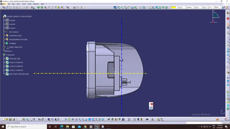
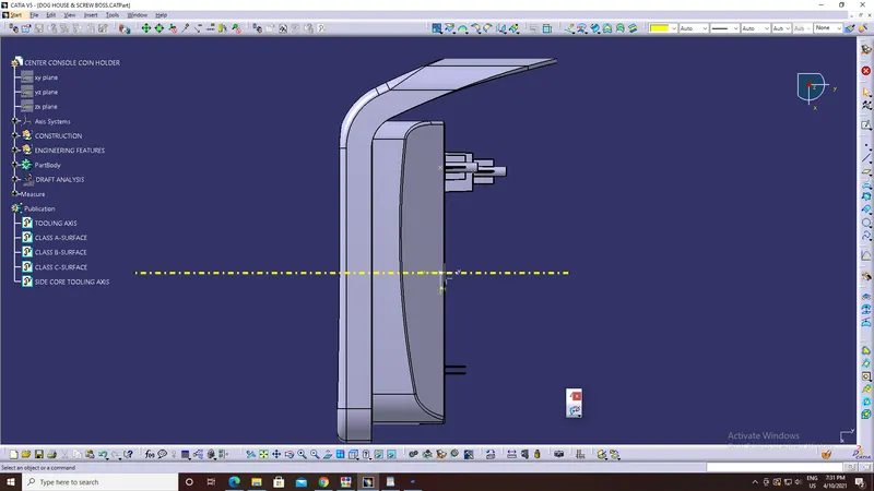
Screenshot of solid component in different orientation:
Isometric View:
Front View:
Right View:
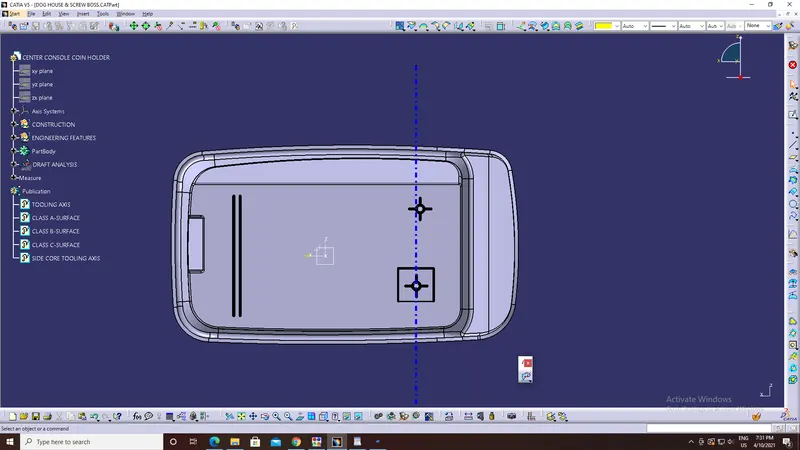
Left View:
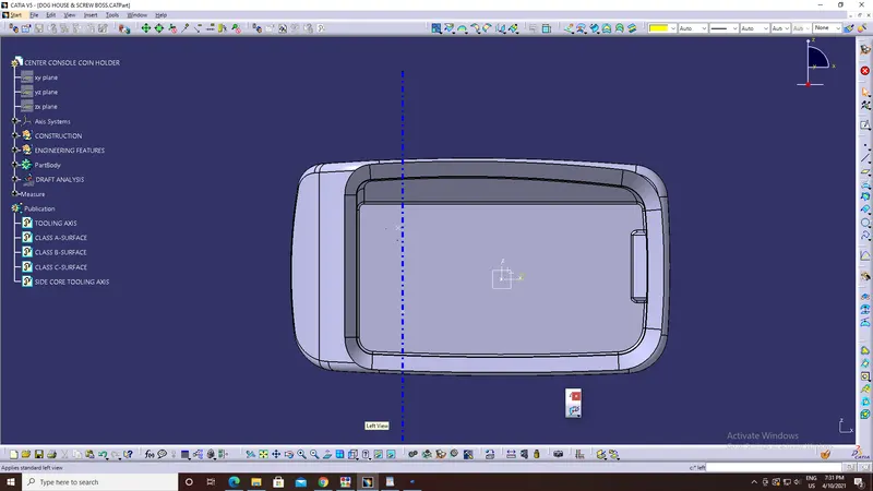
Top View:
Conclusion:
The Class A-Surface is not drafted and this creates problem in manufacturing process, so need to inform the team which has created the class A-surface and get a drafted surface. Due to the error in Class A-Surface, the draft analysis results are not satisfied.
Ribs, Screw Boss and Doghouse are created on the B-side of the surface and draft analysis is performed on final component.