Week 9 - Attachment Feature Creation - Challenge 2
Attachment Feature Creation - Challenge 2
Objective
To Create the Dog House for the Door Trim considering the design rules.
Software Used
Catia V5
Design Consideration
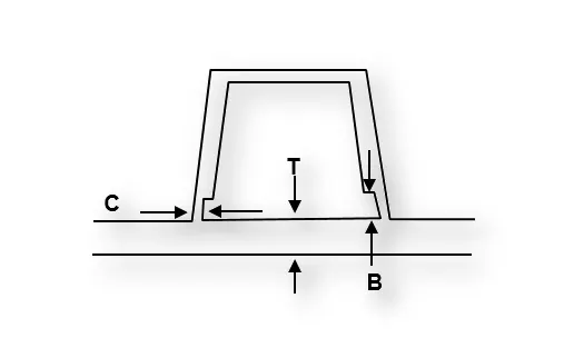
● Height of the Dog House - Maxiumum of 55 mm
● Thickness of the Dog House (t) - Same as component wall thickness
● Coring Height (B) - 3 mm to 6 mm
● Coring Thickness (C) - 40% of Wall Thickness of the component
● Thickness of the Component - Given as input
● Length and Breadth of the Dog House can be decided upon the application
● Inner Fillet of Dog House (Thickness t) - 0.5 mm
● Outer Fillet of Dog House (Thicknes t) - t + 0.5 mm
● Inner Fillet of Dog House (Thickness C) - [ t + 0.5 mm] - 40% of Wall Thickness
● Outer Fillet of Dog House (Thicknes C) - t + 0.5 mm
● Fillet for the Corting Face - 0.25 mm (or) 0.3 mm
● Draft Angle for Dog House - 0.5 degrees (both outer & inner)
Overview Design Life Cycle Automotive Industry
The Stages Of Design Life Cycle Are
-Concept Sketches:
Concept Sketches Are Rough Idea Of Free Hand Sketch Obtained Through Styling Team And Will Be Used To Prepare The Model. It Is Usually Done Through Pen And Paper And Through The Painting Software. This Is Will Be Used To Generate The Concept For Preparing The Model By Incorporating Various Styles And Information Obtained Through The Stakeholders
Class A Creation:
After Finalizing The Concept The Sketches Are Usually Worked In Software’s Such As Auto-Desk Alias To Create Class A Surface
Clay Modeling :
The Class A Surface Is Concurrently Worked By Clay Modelers To Brainstorm And Benchmark The Styling Of The Product And Later The Concept Is Validated By Bringing Up a Rough Clay Model And Then It Is Passed On To The Design Team For The Preparation Of New Product Design (Npd) Cad.
Npd Cad:
This Where The Development Of Surfaces To Parts In Cad Kick Off And Design Engineers Involvement Is Vital In This Stage.
The Designers Will Work On The Input Class A Surfaces Which Are Validated From The Feasibility Team
The Procedure Followed In Creation Of The Plastic New Product Design Are
Tooling Axis
B Surface Creation
C Surface Creation
Closed Body Creation
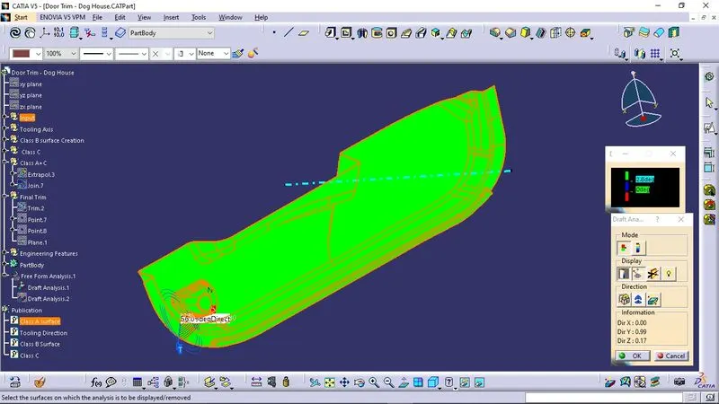
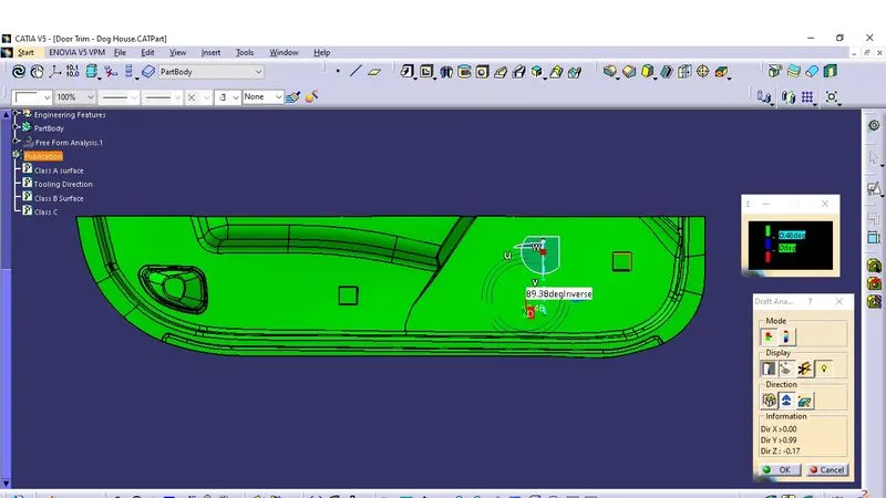
Draft Analysis
Tooling Axis:
The Given Class A Input Is Analyzed To Envision The Part To Manufacture And Tooling Axis Or Tooling Direction Or Die Line Is The Direction That Molds Pull Apart In Injection Molding. There Are Two Mold Pieces Names Core And Cavity. Thus Tooling Direction Determines Mold Separation And Also Becomes Vital In Developing The Plastic Product Which Is Drafted To Desired Nominal Angle For Feasible Clearance And Ejection Of Final Part From The Mold.
-A Reference Point Is Created Along The Surface Zero And New Axis System Is Created
-The X Direction And Y Direction Along The Class A Were Used To Create Tooling Direction
-Finally The Tooling Axis Is Created By Bisecting The Two Lines And It Is Published. Class A Surface As Input Using Surface Operation Commands Class B Is Developed
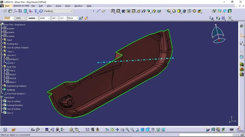
-The Tooling Axis Determines The Direction Of Class C Boundary Swept With Draft Direction.
-When Viewing From Tooling Direction Normal All The Parts That Are Drafted Should Be Visible So It Gives An Rough Idea To Determine Product Manufacturing In Injection Molding
Class A surface
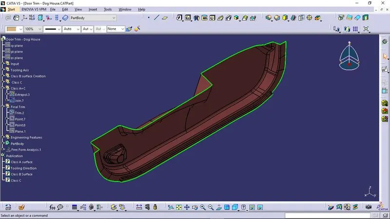
Tooling Direction
Initial Draft analysis
Class B Surface
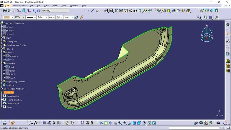
Class C Surface
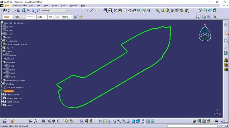
Final Output
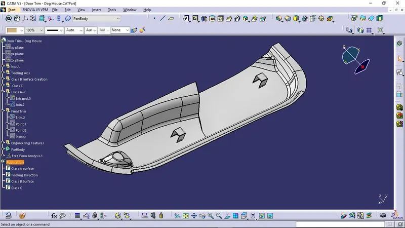
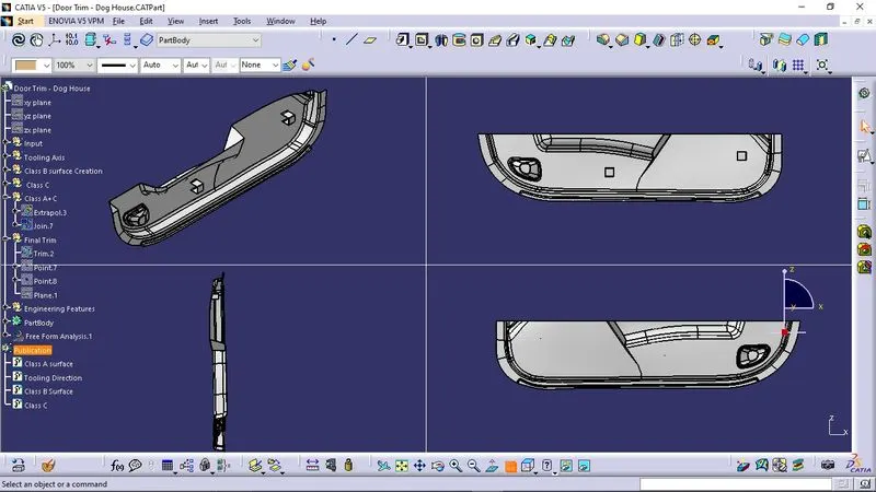
Conclusion
A complete Understanding of creation of Doghouse is thus concluded.