Week 9 - Attachment Feature Creation - Challenge 2
CONSOLI & RIB DESIGN
The class A surface is provided to us, we need to create B surface and C surface and create a solid model. At the end we have to do draft analysis to check whether the component is manufacturable or not.
Draft angle
The draft angle is the amount of taper fa=or molded or cast parts perpendicular to the parting line. It can be measured in degrees or mm\mm (in\in)
Tooling direction
Tooling direction is the main consideration for plastic parts and mold parts because it defines the movement of the mold part and the possibility of the part coming out from the mold part.
Tooling axis
The axis analysis which the mold or core and cavity opens. The draft analysis within catia v5 will help you quickly gather the draft angle on multiple surfaces without the need for tedious manual measurements. The draft analysis allows the user to easily analyze a part for proper draft angle.
Importance of drafting.
When developing parts for plastic injection molding, applying a draft (or a taper) to the faces of the part is critical to improving the mold ability of your part, without it parts run the risk of poor cosmetic finishes and may bend, break, or warp due to molding stresses caused by the plastic cooling. Equally important, an absence of draft may prevent parts from ejecting from the mold, damaging not only the parts but possibly the mold itself-a costly and time-
CLASS A SURFACE
- Visible surface and aesthetic look
- Surface with textures
- Surfaces provided by customer(OEM)
- Don’t have any features like(rib,snap, bosses, etc) on class A surface
- Class A surface is made from scanned data with different software like alias etc.
- Surface which is having CURVATURE CONTINUITY IS CALLEX class A
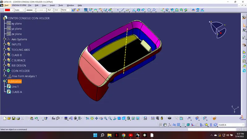
TOOLING AXIS.
this axis is created by base surface of class A
After receiving the class A surface model the connectivity of surfaces was checked. The connectivity of the surface can be checked in three different ways
Join operation
Boundary operation
Disassemble operation
After verifying the connectivity of surfaces these operations were deleted.
Determining the tooling axis
The tooling axis is the axis along which the mold or core and cavity opens. The tooling axis for a model has to be decided so that no additional works are needed on it which helps to reduce the cost.
A point is made on the base wall of the class A surface. An axis system is introduced on to that point.
Intersection of one axis plane and body is created. Since one surface is at 0 degree the axis is created at the center at the center of the surface.
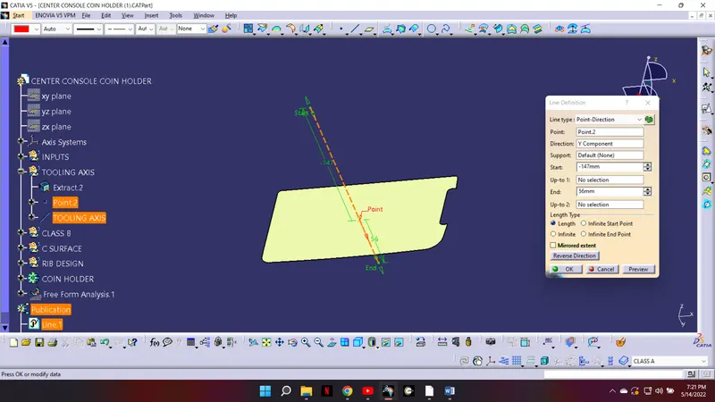
DRAFT ANALYSIS IN THE TOLLING DIRECTION.
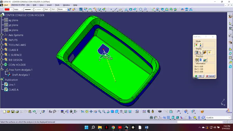
Now we have to perform the draft analysis in the required tooling direction.
CLASS B SURFACE
- Invisible surfaces.
- Surface mostly don’t have textures
- The surface needs to be created according to the class A surface
- Having all features (rib, snap, etc) in B surface only.
- Surfaces which is having TANGENT CONTINUTY IS CALLED B SURFAE
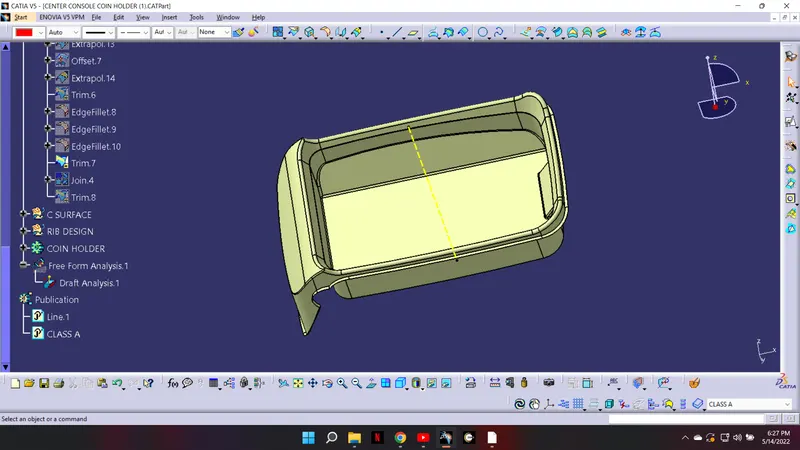
Now we have create B surface which is the engineering surface. All the features like holes embosses are created on the B surface. For that we have to extract A surface it and then trim it and apply the required fillets.
CLASS C SURFACE
- Class c finish allows more imperfections than class A or B.
- It is often specified for interior surfaces not readily visible surface that will be covered by another part when assembled, or surfaces that the customer feels do not need to meet a high cosmetic finish.
- It is used for parts or surfaces which are not views after installation or viewed only for service.
- The distance between each point of the edges of two neighboring patches in no more than 00.5mm
- The angle between the tangents to the surface on the edges of two neighboring patches is no more than 30 (0.5)
- Shape tolerance is not applied.
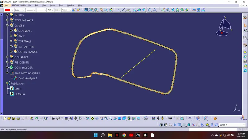
We have to create c surface is the width of A , C SURFACE
CLASS A+C SURFACE

Trim both the A+C surface with the class B surface. The by using close surface command from the part workbench, turn the component into a solid.
SOLID COMPONENT
both the A+C surface with the class B surface. The by using close surface command from the part workbench, turn the component into a solid.
RIB DESIGN.
Ribs are a feature in plastic injection molded parts. They are thin extensions that run perpendicular form a wall or plane. They are commonly used to provide additional support and strength to a part.
THICKNESS OF THE RIB.
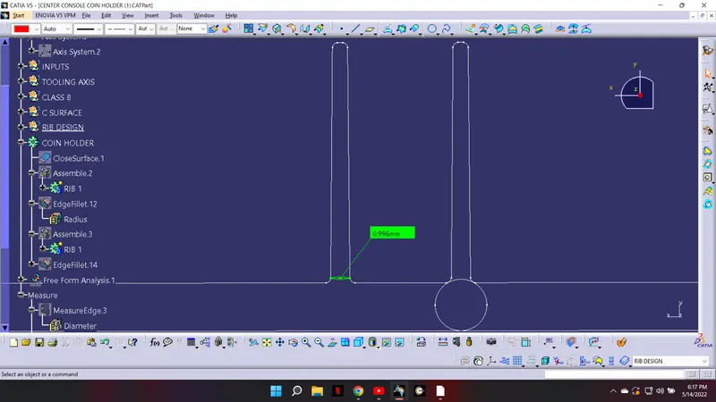
The rib thickness should be 0.4 ( thickness of the component) 0.4 *2.5= 1mm
RIB HEIGHT.
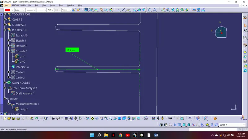
The height of the rib should be < 5T=5x2.5=12.5. Here if is coming out be 10 mm which is less than 12.5 so it will do.
RIB THICKNESS AT TOP.
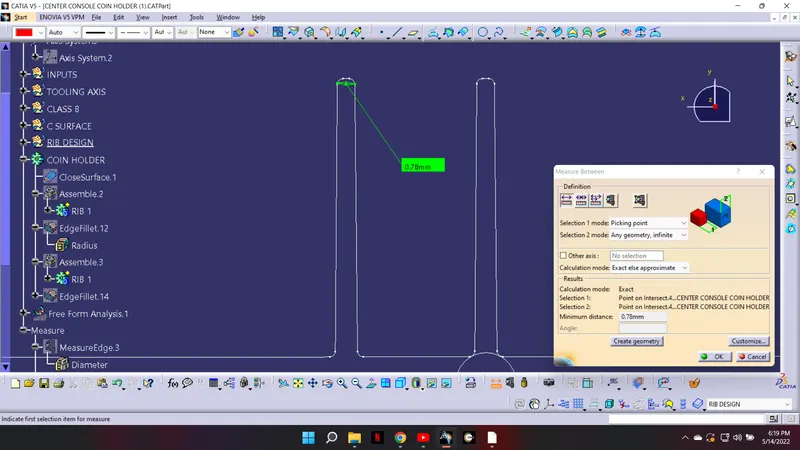
The rib thickness at tip should be >0.75.
FILLET RADIUS.
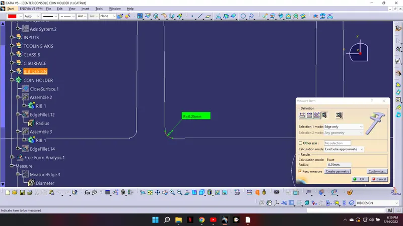
The fillet radius should be max 0.25.
RIB ROOT THICKNESS.
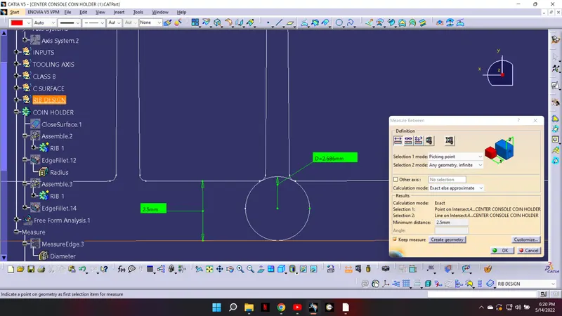
The rib root thickness should be +_ 30 % of the component thickness. The rib root thickness is calculated by drawing of the circle. Here the dial of the circle is 2.6 mm and the thickness of the thickness of the component is 2.5mm. so the 2.6 mm is within the permissible limit of +_ 30 % of the component thickness.
SPACEING BITWEEN THE RIBS.
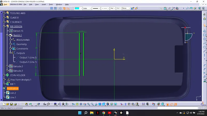
Now to find the spacing between the two ribs. The height to space between the ribs ratio should be 3:1. Here the height is 10 mm and the space to be find out. By calculating we will get. The minimum distance should 2:1 perfect.
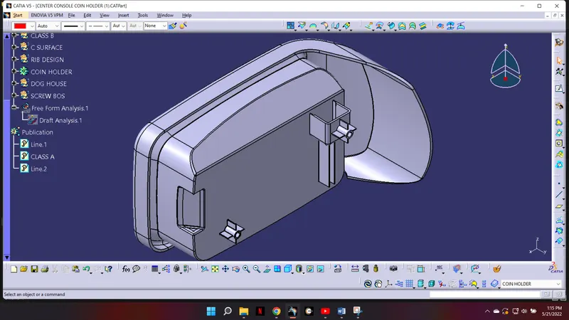
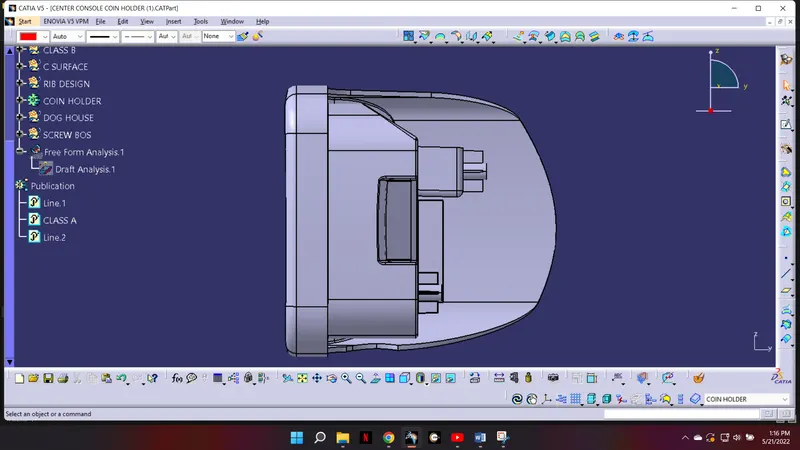
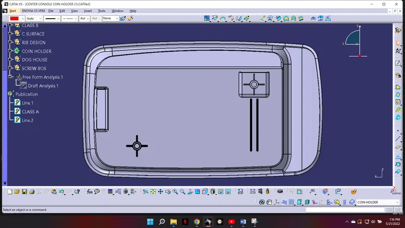
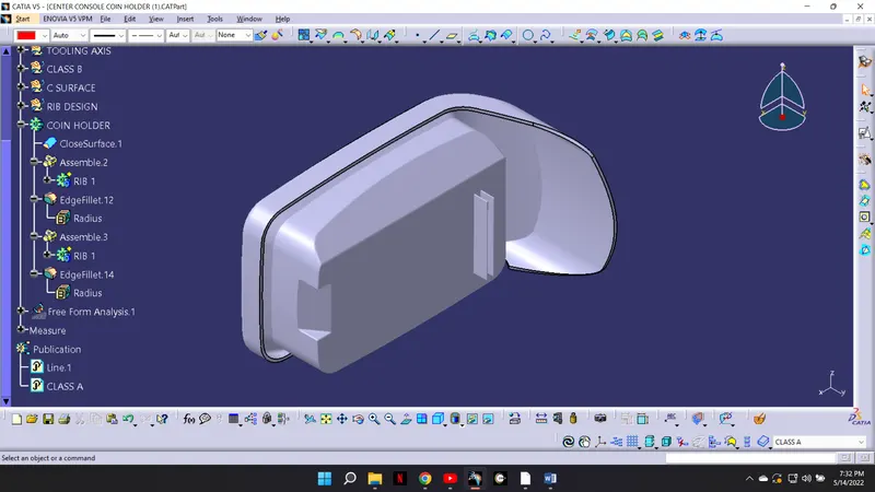
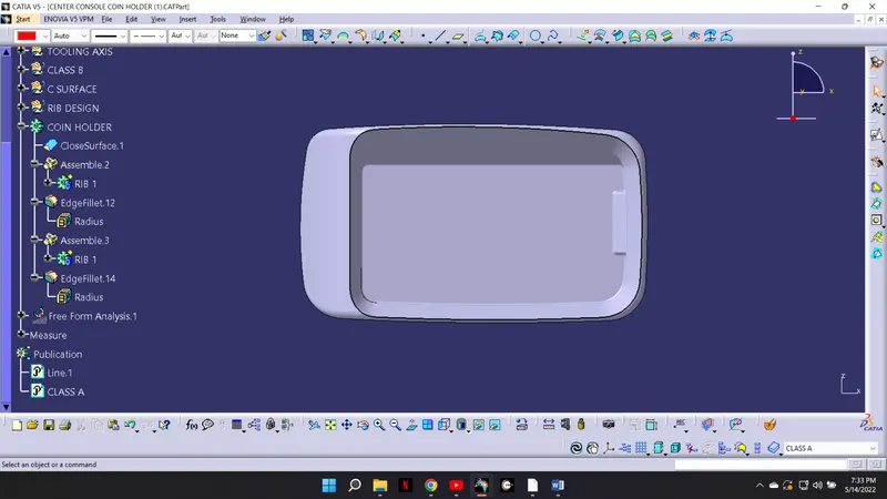
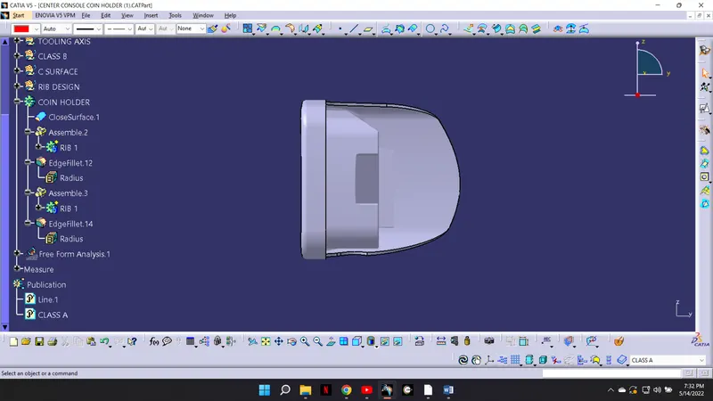
DRAFT ANALYSIS OF THE WHOLE COMPONENT.
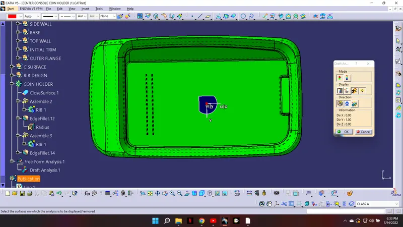
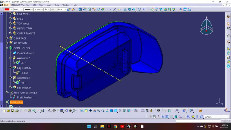
IAOMETRIC VIEW
FRONT VIEW
SIDE VIEW
SCREW BOSS.
Minimum fillet radius
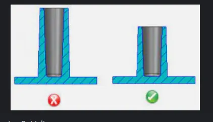
A fillet of a certain minimum radius should be provided at the base of a boss to reduce stress. The intersection of the base of the boss with the nominal wall is typically stressed and stress concentration increases if no radii are provided. Also the radius at the base of the boss should not exceed a maximum value to avoid thick sections. The radius at the base of the boss provides strength also, the radius at the base at mold. The recommended value for the radius to the base of a boss is 0.25 to 0.5 times nominal wall thickness
RADIUS AT BASE.
Providing a radius on the core pin helps in avoiding a sharp corner. This not only helps to mold but reduces stress concentration. It is recommended that the radius at the hole in the boss should be 0.25 to 0.5 times nominal wall thickness
MINIMUM DRAFT.
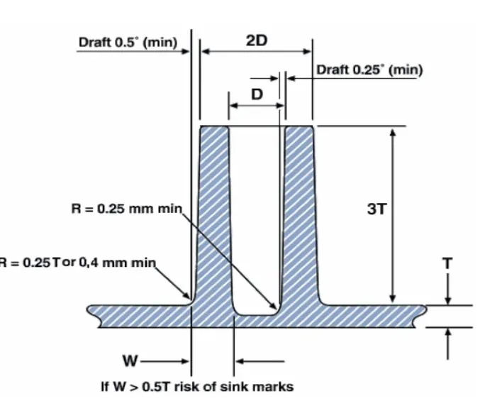
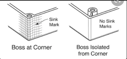
An appropriate draft on the outer diameter of a boss helps easy ejection from the mold. The draft is required on the walls of a boss to permit easy withdrawal from the mold. The recommended value for the minimum draft 0.5 degree
DRAFT ANALYSIS BOSS
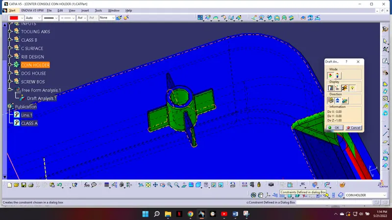
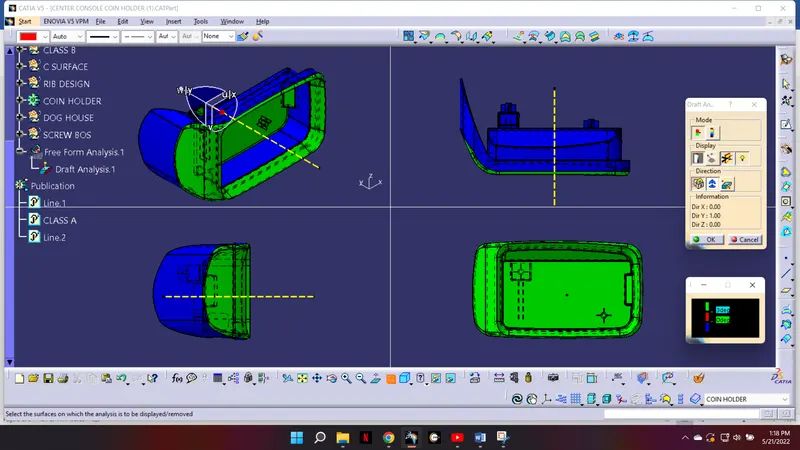
DESIGN
- Circular sketch is made on the bottom side of coin box. It is then extruded to a height of 12 mm
- Ribs are added to it by drawing two lines crossway and extrapolating it with thickening
- Union trim to cutout the unwanted portion
- Edges are properly filleted of radil 0.25
- It is then added to the main body.
- A copy of the screw boss is made and translated to a new position
DESIGN RULE OF DOG HOUSE
Doghouse wall thickness at the intersection of the part wall should be 40% or less then the main wall stock
The height of B should be between 3 to 6 mm
DESIGN
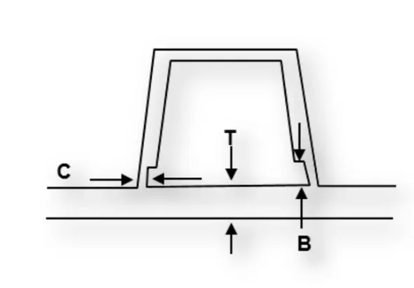
- A rectangular sketch is made with one side opened.
- It is then swept to a certain height, trimmed the top with an offset of the base to close the top
- Thickness is added to the made box, the walls are drafted inside and outside along tool axis and side core axis
- Fillets are made in appropriate places.
- B section is made up to height of 4 mm. the section made is trimmed with the body
- The screw boss is translated to a height so that it lies above the dog house
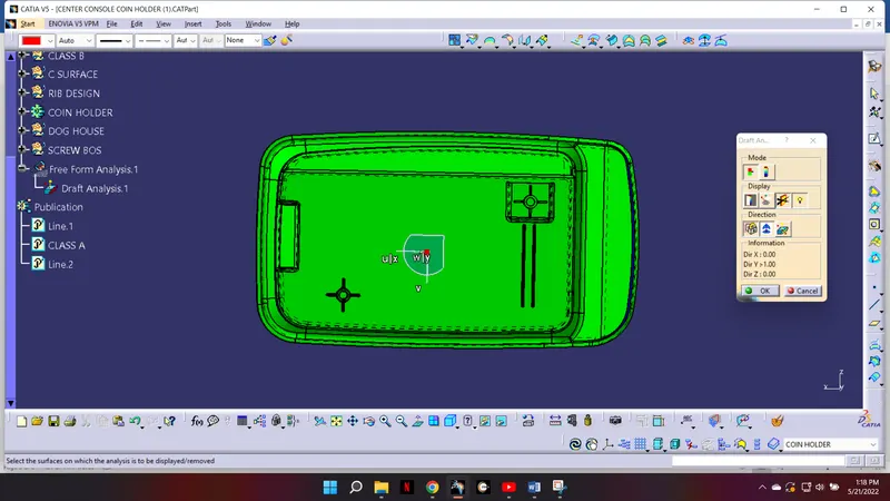
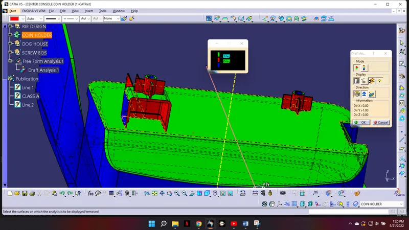
- Draft analysis is made in the end to check the draft along the tool axis and side core axis
DRAFT ANALYSIS OF DOG HOUSE
ISOMATRIC VIEW