Week 9 - Attachment Feature Creation - Challenge 2
DESIGN AND DRAFT ANALYSIS OF SCREW BOSS AND DOG HOUSE
AIM
To design the screw boss and dog house, and to perform draft analysis.
PROCEDURE
Screw bosses and dog houses are B-side feature of the plastic parts, which helps in fixing of the plastic components together. There are several rules to be followed during designing the screw boss and dog house.
There rules are followed for avoiding various defects in the plastic parts produced, and these rules are given below
General Guidelines for Bosses:
- Draft - 0.5 degrees on walls of boss
- Thickness - Typically 40%* of the nominal wall at the base.
- Height to Diameter Ratio - 3:1
- Radii - 0.25mm maximum radii.
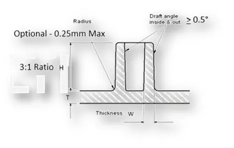
General Guidelines for Dog house design:
Dog houses are always to be designed according to the following design rules
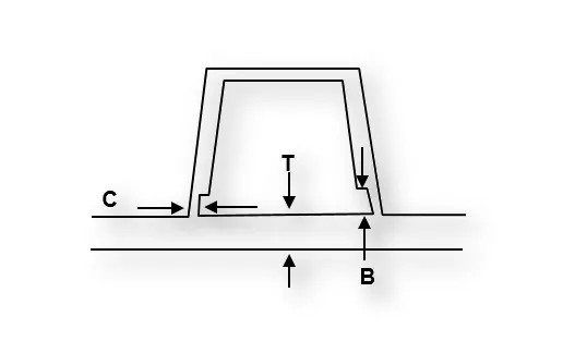
"C" is where the doghouse contacts the backside of the surface
- Doghouse wall thickness at the intersection of the part wall ( C ) should be 40% or less than the main wall stock ( T ).
- Height of ( B ) should be between 3.0 – 6.0 mm
To design the screw boss we have to use the bottom surface of the coin holder, and we have to sketch the inner and outer circle of the screw boss, and there is also a calculation to draw the screw boss.
The inside diameter of the sketch should be according to the thread pitch value in this case it is 5.2mm for M6 screw and the outside diameter determines the screw boss thickness,
The formula for screw boss thickness W=0.6*T
Here T represents wall thickness of the component, and the thickness of the screw boss is w = 0.6*2.5
= 1.5
The above shown value is thickness of the screw boss we need to multiply this value by 2 and add this value to the inner diameter of the screw boss then we will get the diameter of the screw boss is 2(1.5) + 5.2 =8.2mm. Below image shows the sketch of the screw boss
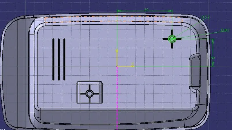
Then we have to calculate the height of the screw boss, formula for calculating the height of the screw boss is given below,
The ratio between the height to the diameter should be less than 3, it is stated as H/B<3, therefore H < 3 * 5.2
H < 15.6, so we can take the height as 12mm.
So we have to pad it for 12mm.
Then we have to design the rib for the screw boss, this rib also should follow the plastic design rules,the rib thickness should be 0.4 times the thickness and should have a draft of 0.5degrees, and should have the height less than are equal to five times the thickness of the plastic part. The sketch for the rib is also shown below and we have to use the thick profile option to design the rib and make sure that thick profile option is enabled.
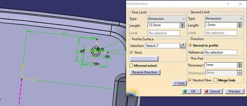
While designing the screw boss we always ensure that we are following the proper tree structure, as shown below
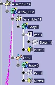
In this tree structure the features are assembled inside the part body and this part body is assembled to the main body, always follow this tree structure and ensure that we are using correct Boolean operations, the main advantage of this tree structure is we can copy and paste as result the entire screw boss, and we can move it where ever we want by using the translate options.
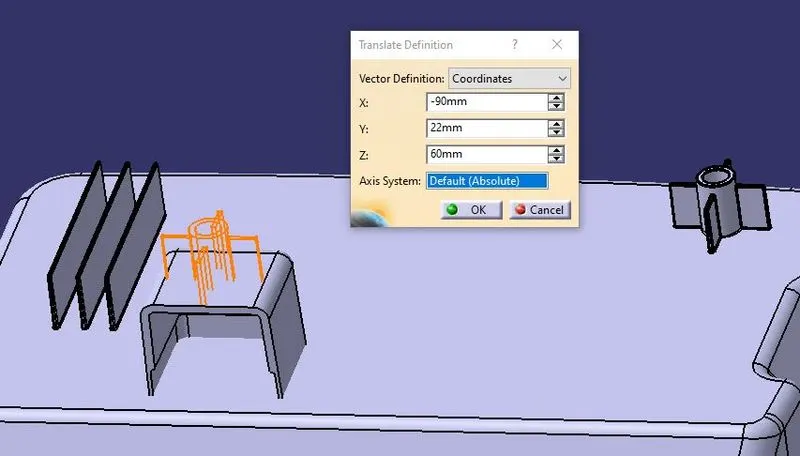
In the above image the orange colour highlighted area shows that the new position of the pasted screw boss.
Then we have to design the dog house, for designing the dog house we need to follow the plastic part design rules and the draft angle for the dog house should be 1.5degree and all the internal faces should have the 0.5degree draft,
The joining area of the draft is at the c area should have 40 percent or less than the 40 percent of the wall thickness of screw boss, and the height of the screw boss should be between 3-6mm otherwise the week steel condition will occur in the mould so it leads to cracks so it is always required to have 3-6mm height.
The sketch for the dog house is shown below,
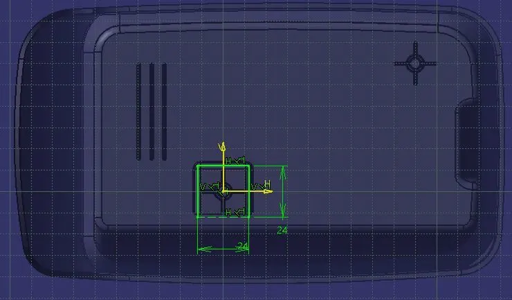
And use the sweep command to create the surface extrude of the dog house and the direction of the sweep should be along the tooling axis, and we have to ensure that we are selecting the correct direction for the screw boss as shown in the image.
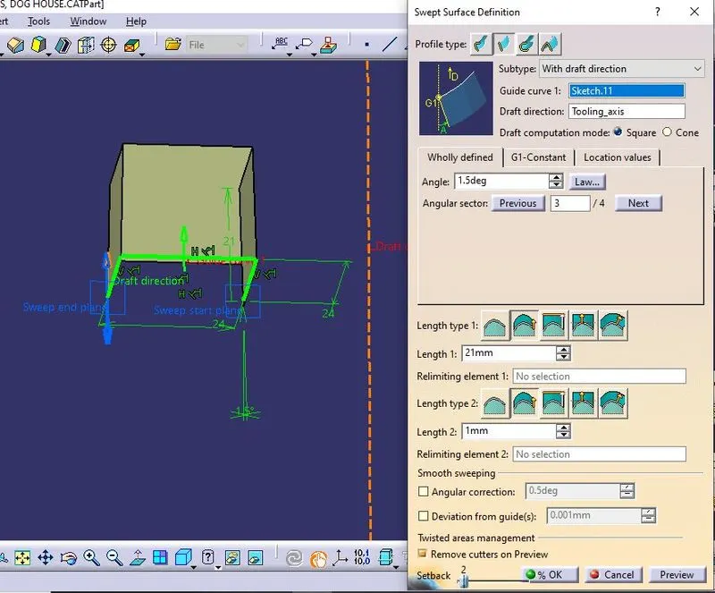
And we have to extract the bottom surface of the coin holder and use it to trim the top side of the dog house, then we have to use the thick surface command to add thickness to the outside of the surface, it is shown in the below image
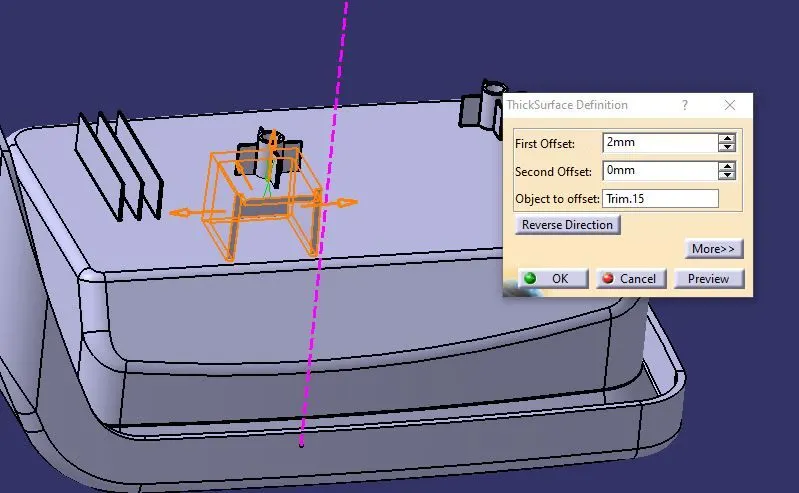
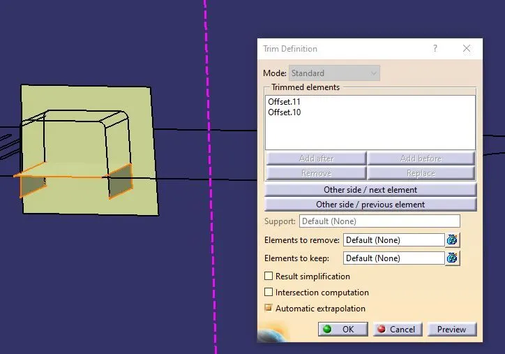
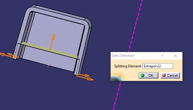
And always make sure that we are using the correct fillet values and we have to form the small thickness area where the dog house is attached to the B-side of the component, for that we have to use the extract command and extract the inside surfaces of the dog house and offset the base extract of the coin holder to 2.5mm and trim the correct portion, and split the solid dog house area with the surface trim using the split command in the part work bench.
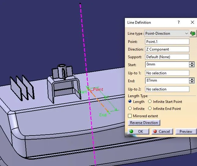
We need to give draft for the outer side walls and inner side walls, while giving fillets to the outer side wall we have to give the tooling axis as pulling direction, and for the inner side walls we have to create the tooling axis according to the movement of slider, for creating the side core tooling axis we can use the point and already available tooling axis, and use the direction as perpendicular to the main tooling axis, and we need to select this tooling axis for the draft pulling direction.
Always make sure that we have given draft to all the faces inside the dog house, and we have to give the draft to the small face inside dog house locator also, and the draft value should be 0.5 for the inside faces of the dog house.
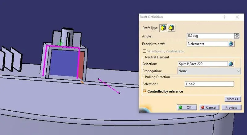
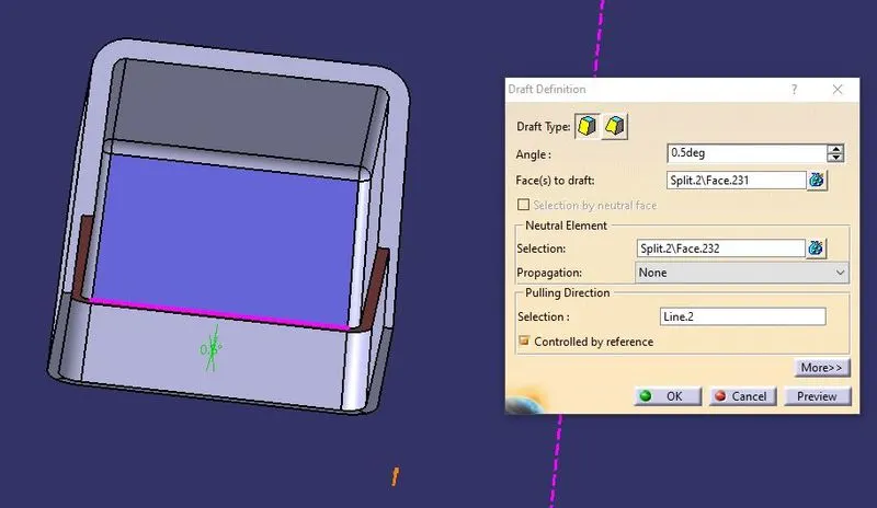
After designing the dog-house we have to use the proper Boolean command to maintain the proper tree structure,
Now we have to perform the draft analysis on the finished part for this draft analysis we have to use the main tooling axis and the side core tooling axis, after creation of the tooling axis we have to perform the draft analysis. For making draft analysis we need to give material mode for the part
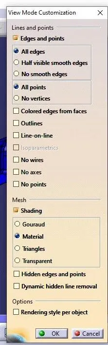
After entering into material mode we have to select the draft analysis on the insert dropdown analysis tab, in that draft analysis we have to select the compass icon shown on the Direction tab’s second icon and we have to place the compass from the screen and place it along the tooling axis.
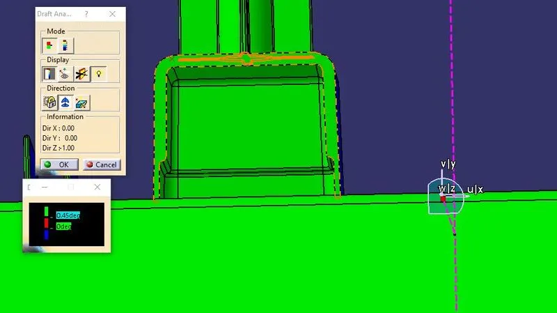
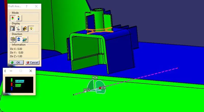
The colour code shows the draft given on that surface, the colour codes shown here of green colour is above 3degree draft, here the draft given on the surface is 9degree so the part is shown in green colour.We have to check all the surfaces of the dog house is shown in the correct draft values according to the colour codes according to the tooling axis selection of the draft analysis.
CONCLUSION
Thus the screw boss and the dog house are designed according to the plastic design rules and draft analysis is also performed.