Week 9 - Attachment Feature Creation - Challenge 2
BOSS AND DOG HOUSE DESIGN
INTRODUCTION: Boss features are commonly found in injection moulding designs. They are used to aid in the assembly of moulded parts by providing a channel for a screw.
Dog house is a feature that helps you to avoid sink marks.
OBJECTIVE: To create the boss and dog house for the centre console coin holder considering all the design rules.
METHODOLOGY: We get the component and with the help of the design rules for screw boss and dog house we design the following, then after that we do the draft analysis.
DESCRIPTION:
Screw boss design: Bosses find use in many parts designs as points for attachment and assembly. The most common variety consists of cylindrical projections with holes designed to receive screws, threaded inserts or other types of fastening hardware. As a rule of thumb, the outside diameter of bosses should remain within 2.0 to 2.4 times the outside diameter of the screw or insert.
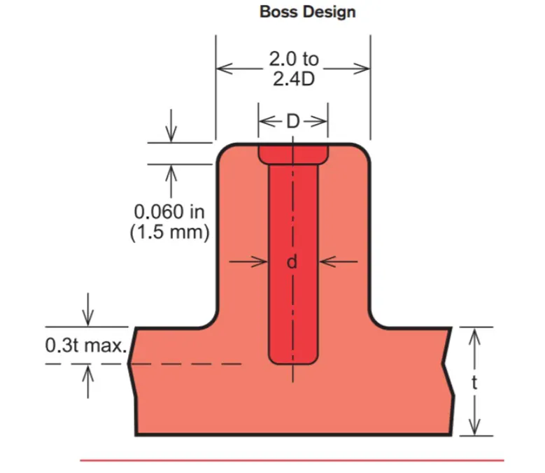
Typical boss design
To reduce stress concentration and potential breakage, bosses should have a blended radius, rather than a sharp edge at their base. Larger radii minimize stress concentration but increase the chance of sink or voids. Specifying smaller screws or inserts often prevents over lay thick bosses.
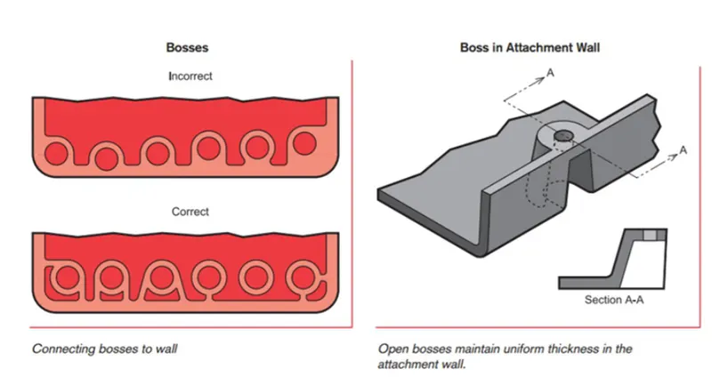
Avoid bosses that merge into sidewalls because they can form thick sections that lead to sink. Instead, positon the bosses away from the side walls and in needed, use connecting ribs for support.
Consider using open boss design for bosses near a standing wall. Avoid bosses that merge into the side walls because they can form thick sections that lead to sink. Instead position the bosses away from the side wall and needed use connecting ribs for support. Consider using open boss design for bosses near a standing wall.
Normally, the boss hole should extend to the base wall level, even if the full depth is not needed for assembly. Shallow holes can leave thick sections, resulting in sink or voids. Deeper holes reduce the base wall thickness, leading to filling problems, knit lines or surface blemishes. The goal is to maintain uniform thickness in the attachment wall because of the required draft, tall bosses those greater than 5 times their outside diameter can create a filling problems at their top or a thick section at their base.
Rules:
- W = 0.6 * T
Measure base thickness of rib at tangent of radius if radii are modelled in.
The larger the area at the base of the rib, the more retained heat.
The retained heat causes more shrinkage which causes sink.
- Optional rib fillet radius – 0.25mm maximum
Must not violate 40% thickness requirement
- Draft 0,5 degree on both inside and outside of the boss
- Height to diameter ratio = H/B < 3
- Boss gussets must meet rib guidelines
- Need to plan ahead of ejection
Dog house design: Dog house is an engineering feature used in plastic trim design. Dog houses are used as supporting feature. Dog house is a feature that helps you to avoid sink marks.
Rules:-
- Dog house wall thickness and sink saver
“C” is where dog house contacts backside of surface.
Dog house wall thickness at intersection of part wall (C) should be 40% or less than main wall stock (T)
Height of (B) should be between 3.0 – 6.0 mm
- Dog house height:-
Minimum height (H) of dog house is 6mm
Less than 6mm causes weak steel condition.
3:1 ratio of steel width to height 2:1 is preferred.
- Dog house width:
Minimum dog house width (X) for dog house is 12mm.
- Dog house draft to die draw:
Minimum draft (D) for dog houses 1.5 degree to die draw.
If a slide is being considered this requirement can change to 3 degrees minimum.
Tooling Axis:
For the tooling axis we first inspect by taking a section and then decide which direction would be better for the tool axis.
Then we create a point at the centre of the base and create an axis system. Then we intersect the surface A with the YZ plane. With the intersection we get what we observe is that the side walls of the class A surface are parallel with the vertical axis i.e. there is 0 degree angle between them.
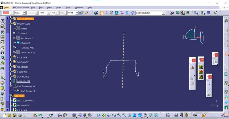
But since it’s a class A surface we have to go the same design since we do not have the authority to change the class A surface design. So we have to go with this draft angle itself.
We create a vertical line along the point created and the vertical axis and this will be our main tooling axis.
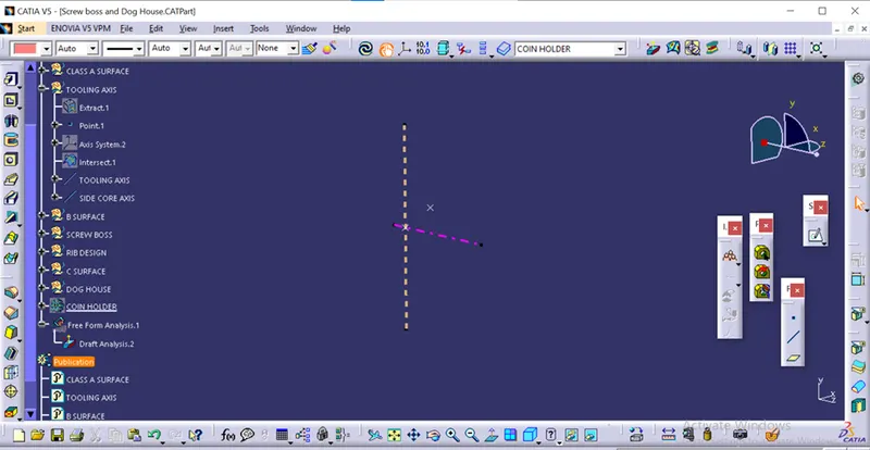
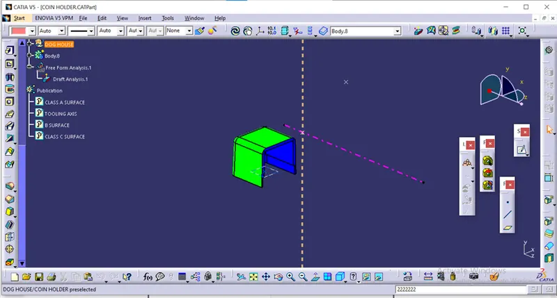
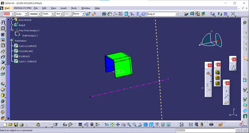
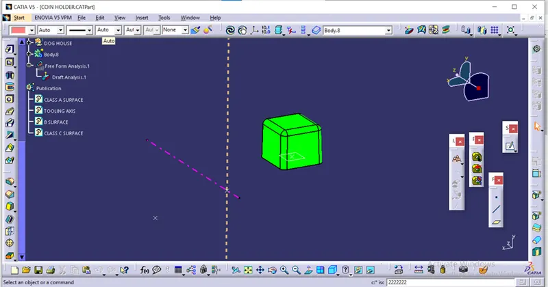
For the dog house we will need a side core to we have to give a tooling axis to the side core as well which would be along the Z axis of the component.
Screw boss design:
We draw a sketch for the screw boss for the coin holder. We decide the inner diameter of the screw boss to be 5.2mm then according to the design rule for screw boss we get outer diameter to be 8.2mm.
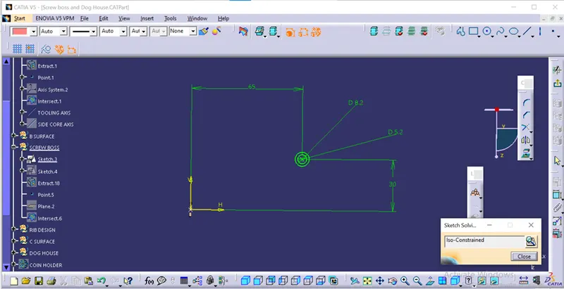
Then we use the pad command up to 12mm. Then we make the rib to support the screw boss.
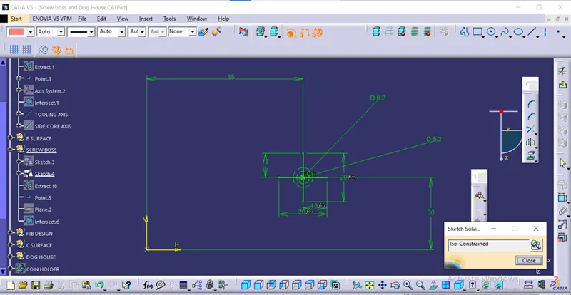
We give draft according to the design rule to screw boss and the rib too. Then we use the edge fillet to fillet all the sharp edges.
We add this body to the main coin holder body. Then we copy the screw boss with the ribs and paste it with the option “as result with link” to form another copy of that body so that we could use the translate tool and move this body. Then we will add this body too with the main coin holder body component.
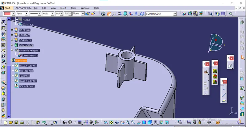
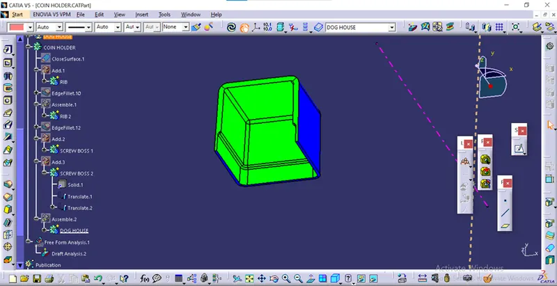
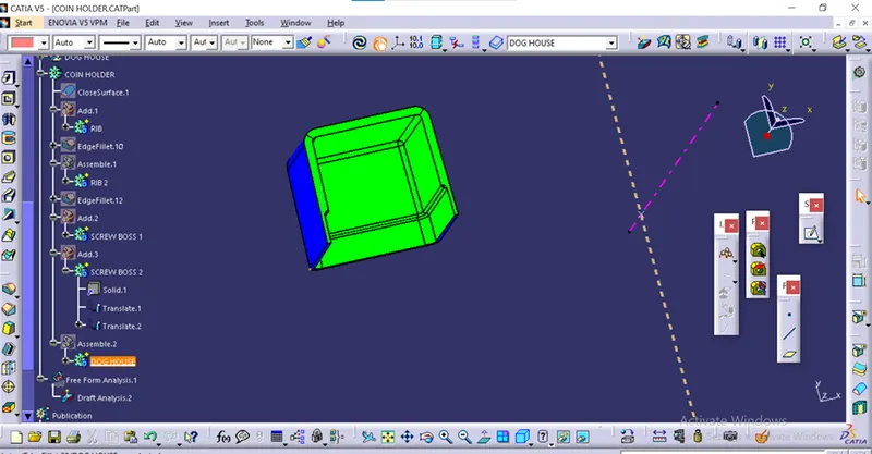
Dog House Design:
First we extract the surface of the bottom base of the coin holder. We sketch the walls around the screw boss, then we use the sweep command to make the walls.
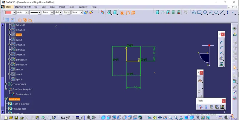
To close the wall from the top, we offset the extracted face upto suitable height and then trim it with the walls. The use thick surface command to make it a solid. We use the split tool to make the surface on the open side even. Then we offset the inner surface and the surface on the bottom and they trim them together so that we can use the split command to the bottom of the dog house thinner according to the design rule. We then draft all the sides of the component and then use edge fillet to fillet all the corners.
We then add this component with the rest of the coin holder body.
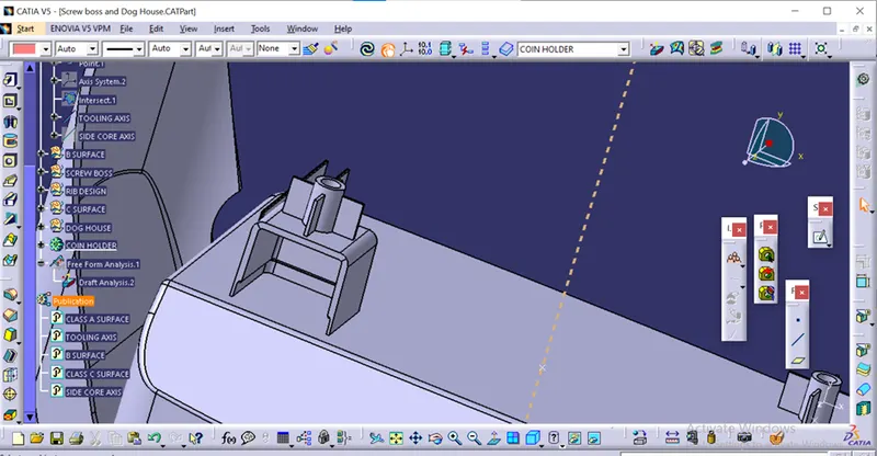
Tree Structure:
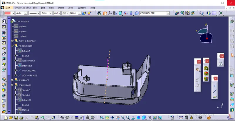
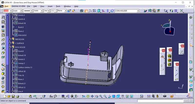
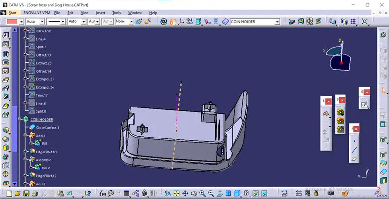
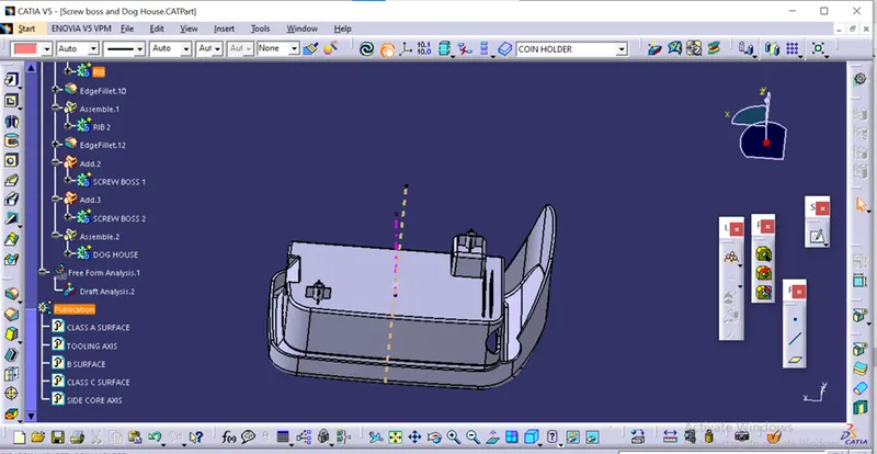
Draft analysis:
After creating the component we do the draft analysis. Before drafting we have to make sure that in the view mode it is selected to the materials.
After selecting the feature draft analysis tool we drag the compass from its position to the tool axis. Then lock the compass, after that select anywhere on the component and it will give you the result.
We change the minimum draft for the component to 1.45 degree.
We can use the running point option to check the angle of the component.
We can even modify the colour according to our preference.
Main tooling axis:
Side tooling axis:
Views:
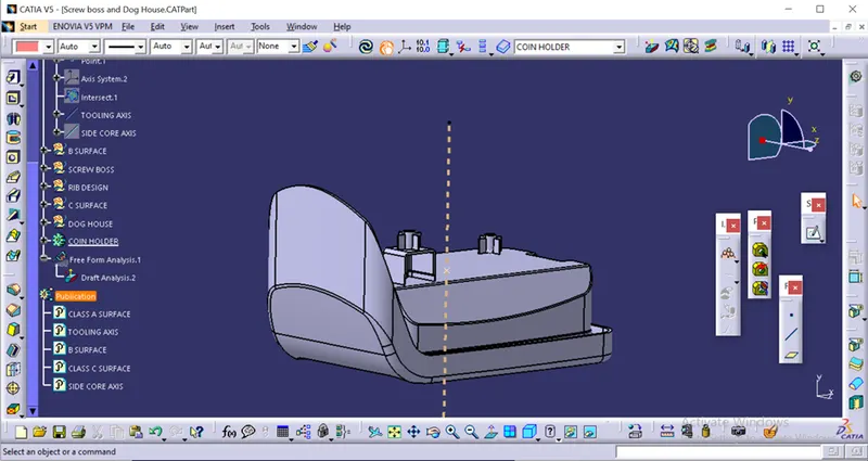
Isometric view
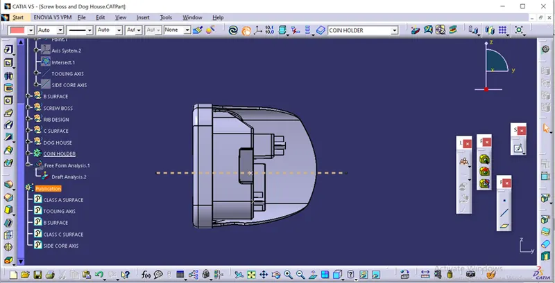
Front view
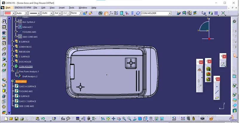
Side view
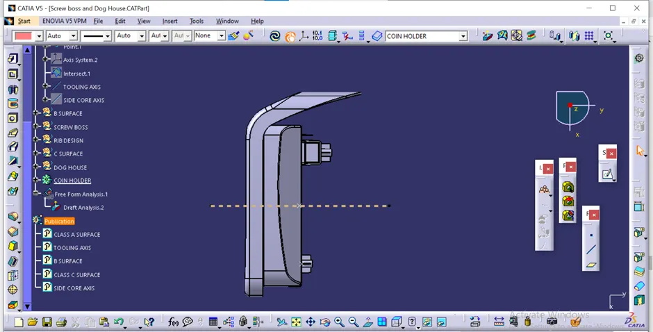
Top view
CONCULSION:
With this we got to learn about the uses of screw boss and dog house and also how design and make the components with the help of the design rules we learned.