Week 9 - Attachment Feature Creation - Challenge 2
DESIGN THE SCREW BOSS AND DOG HOUSE
AIM:
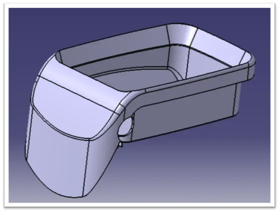
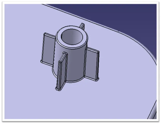
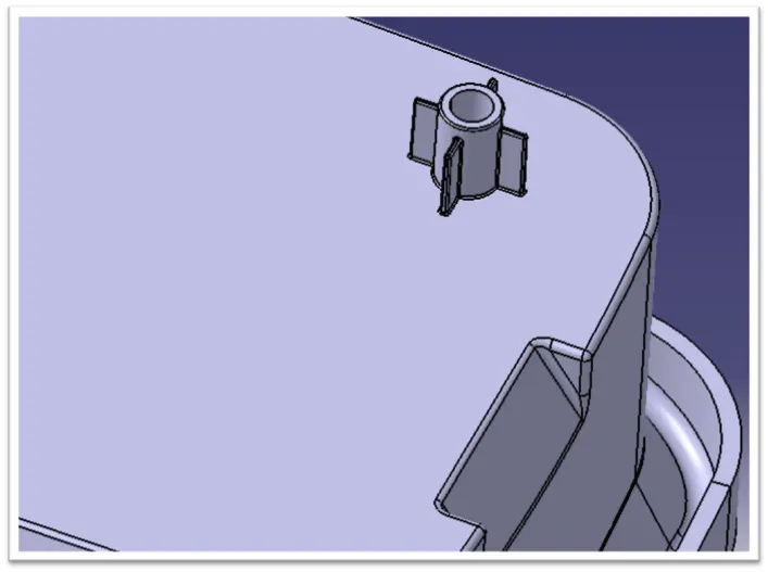
To Design the screw boss and Dog House for the Centre console coin holder.
1.SCREW BOSS:
INTRODUCTION:
Introduction Bosses are protuberances on a plastic part designed to add strength, to facilitate alignment during assembly, to provide for fastening, etc. Currently, many boss design practices are standardized and follow set guidelines. These guidelines are tailored for manufacturing; therefore, the optimal design for the application may not be used. The purpose of this research is to develop a design synthesis methodology for plastic boss design. This methodology and the use of parametric design software will help optimize the design for the application.
A typical boss is an open-topped cylinder, essentially a round rib. Standard guidelines suggest that its wall thickness be between 40 and 60 percent of the thickness of the wall from which the boss rises. If your design requires more strength than this guideline would provide, you should consider ways to strengthen the boss without thickening its walls. The most common of these is to surround the boss with gussets to support and strengthen its walls.
BOSSES:
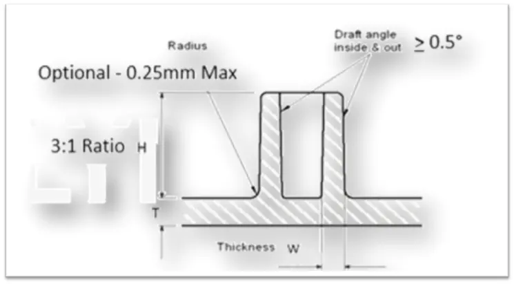
- Bosses are projections designed to accept inserts, self-tapping screws, etc. for use in mounting, fastening or assembling parts
- Typically the boss O.D(Outer Diameter) = 2 I.D(lnner Diameter)
- Allows the wall to increase as the size of the boss increases.
- Wall thickness at base of boss < 60% of nominal wall
- Reduces sink marks and cycle time
- Boss height < 3 x O.D(Outer Diameter)
- Minimizes excess mass at bottom of boss and allows for sufficient cooling of core pin
- Base of boss should be radiused 25 - 50% on nominal wall (minimum of .015-inch)
- Minimizes stress concentration in high stress area.
SCREW BOSS DESIGN GUIDELINES:
1.Minimum radius at base of screw boss:
A fillet of a certain minimum radius should be provided at the base of a boss to reduce stress. The intersection of the base of the boss with the nominal wall is typically stressed and stress concentration increases if no radii are provided. Also, the radius at the base of the boss should not exceed a maximum value to avoid thick sections. The radius at the base of boss provides strength and ample draft for easy removal from the mold. The recommended value for radius at the base of a boss is 0.25 to 0.5 times the nominal wall thickness.
2.Spacing between bosses:
When bosses are placed very close to each other, it results in creating thin areas which are hard to cool and can affect the quality and productivity. Also, if the mold wall is too thin, it is very difficult to manufacture and often results in a lower life for the mold, due to problems like hot blade creation and differential cooling. Hence, it is recommended that spacing between bosses should be at least 2 times the nominal wall thickness.
3.Minimum draft for screw boss outer diameter:
An appropriate draft on the outer diameter of a boss helps easy ejection from the mold. The draft is required on the walls of a boss to permit easy withdrawal from the mold. The recommended value for the minimum draft on the outer surface of the boss is greater than or equal to 0.5 degrees.
4.Boss height to outer diameter ratio (Height):
A tall boss with the included draft will generate a material mass and thick section at the base. In addition, the core pin will be difficult to cool, can extend the cycle time and affect the cored hole dimensionally. It is recommended that the height of boss should be less than 3 times of outer diameter.
5.Minimum radius and chamfer at top of the boss:
A fillet of certain a minimum radius value should be provided at the tip of a boss to reduce stress. Boss should have chamfer on top. A chamfer at top of boss is good lead in for the fasteners.
6.Wall thickness of boss:
Wall thicknesses for bosses should be around 60 percent of the nominal wall to minimize sinking. Wall thickness greater than this can create voids and sink marks and may also expand the cycle time.
7.Standalone screw boss:
Bosses and other thick sections should be cored. It is good practice to attach the boss to the sidewall. In this case, the material flow is uniform and provides additional load distribution for the part. For better rigidity and material flow, a boss should be connected to the nearest side wall.
COMPONENT:
2. DOG HOUSE:
Introduction:
Dog house is an engineering feature used in plastic trim design. Dog house are used as supporting feature. Sometimes other engineering features like snaps; locators etc. Are mounded on them to increase their strength. Dog house are subjected to draft analysis to prevent breakage of the component during ejection from mould cavity. Dog house and other engineering components are built on B – surface.
Design consideration for plastics:
1.wall thickness:
Thick section waste material and are simply uneconomic. So solid shapes that would do the job well in wood or metal must be transformed to a ‘shell’ form in plastics. This is done by hollowing out or ‘coring’ thick parts so you are left with a component which regardless of complexity is composed essentially of relatively thin walls joined by curves, angles, corners, ribs, steps and offsets. As far as possible, all these walls should be the same thickness. Wall thickness guide range is 0..75 mm to 3mm for reinforced materials 0.5 mm to 5 mm for unreinforced materials.
Wall thickness (w)=0.70*(normal thickness of plastic material)
2.corner radii:
Properly designed corners will make a big difference to the quality, strength and dimensional accuracy of a moulding. But there is another benefit too. Smooth curved corners help plastic flow in the mould by reducing pressure drops in the cavity and minimising flow – front break-up.innternal radii should be at least 0.5 and preferably 0.6 to 0.75 times the wall thickness.
Corner radii=(0.6-0.75) * (normal thickness of plastic material)
3.draft angle:
Tooling must be cleared for easy ejection of the component, from the core cavity. Inn order to clear tooling certain value of draft is given to the component. Minimmum of 2-3 deg is provides on all plastic components.
4.fillets:
Fillet on the inner side = 0.25 * thickness of the plastic material
Fillet on the outer side = 1.25 * thickness of the plastic material
Fillet on the coring edges = 0.25 * thickness of the plastic material
Coring thickness = 0.40 * thickness of the plastic material
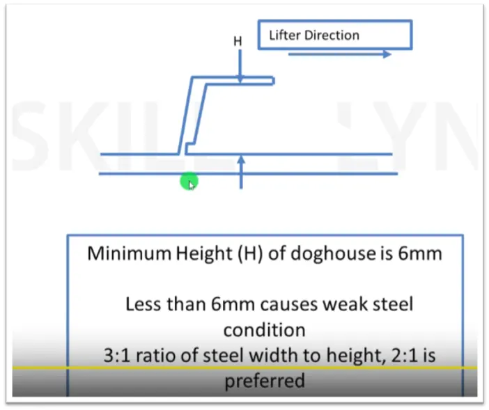
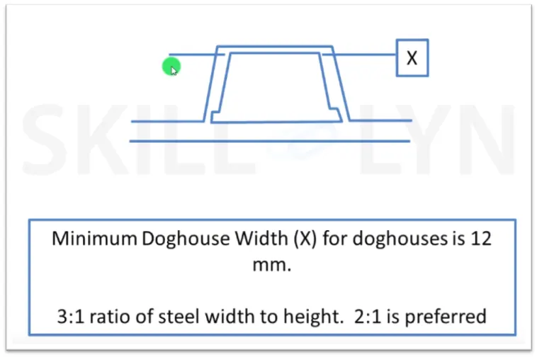
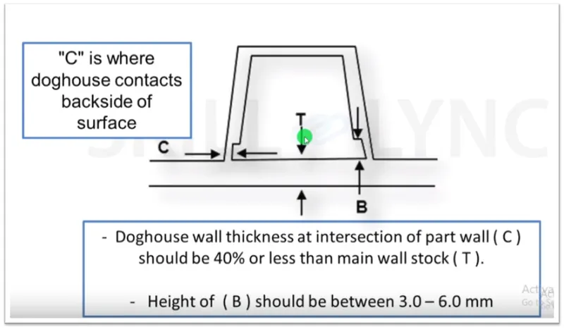
DOG HOUSE DESIGN ON COIN HOLDER
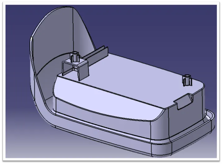
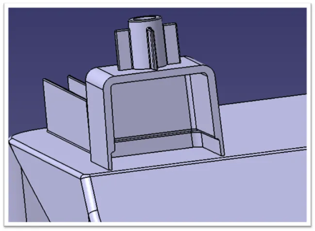
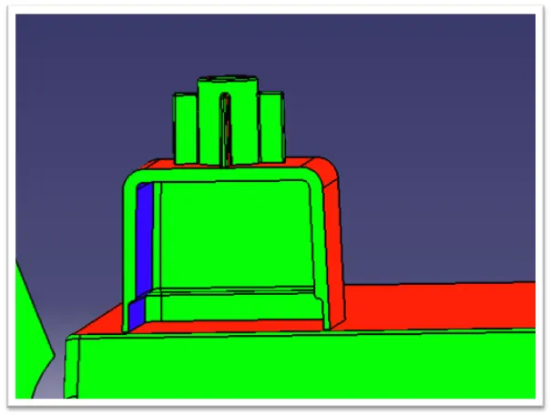
DRAFT ANGLE THROUGH 'Y' DIRECTION
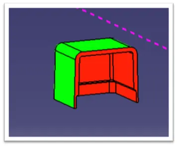
DRAFT ANGLE THROUGH 'Z' DIRECTION
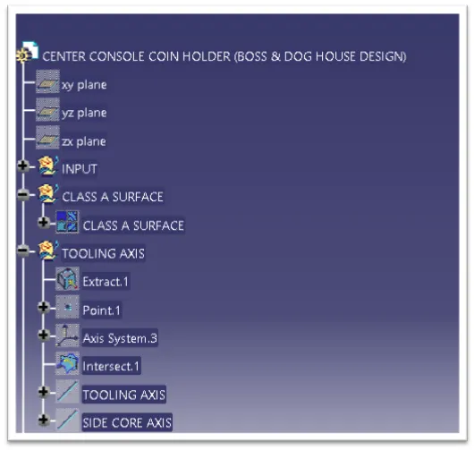
TREE STRUCTURE:
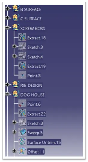
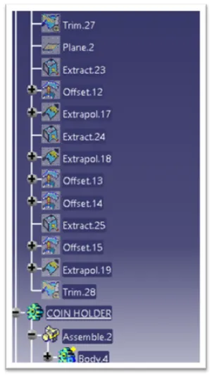
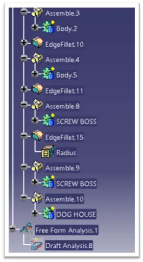
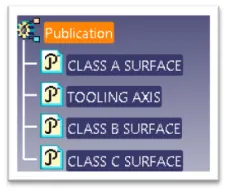
CONCLUSION:
The Screw boss and Dog House has been design following all the design rules.