Week 9 - Attachment Feature Creation - Challenge 2
ANS 1
TOOLING AXIS = It is the axis or direction along which the core and cavity move and the required part ejected along this direction. In this question, we are going to explain making tooling axis by NORMAL TO SURFACE method.
STEP 1 =Selecting the surface along which we need to create the tooling axis.
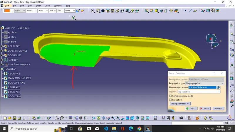
STEP 2 = Creation of point using the point tool using the option on the surface. select the extracted surface and give 0mm in the distance option to create the point in the middle of the surface.
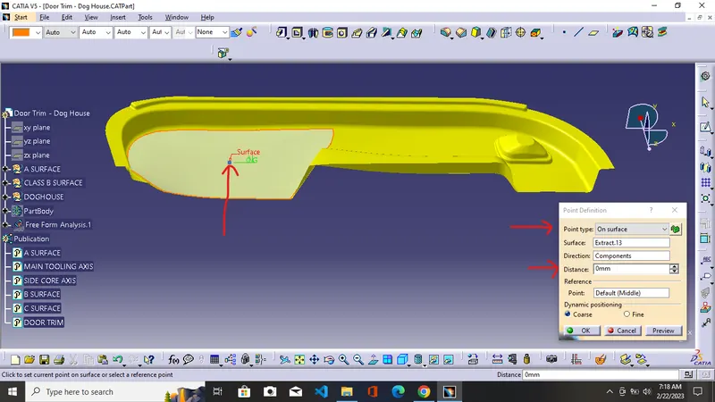
STEP 3 = Creation of the required main tooling axis using the line tool and selecting the normal to surface option to give extracted surface in the reference surface option and the previously created point in the reference point option and obtain the required main tooling axis.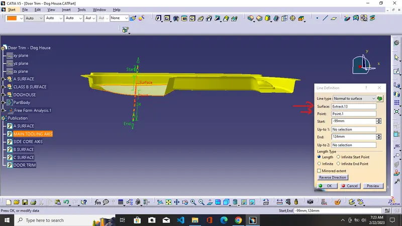
DRAFT ANALYSIS = It gives us information about the parts which tells us which part clears the mold walls easily so as to minimize the machining process in the finished product and final product ejected easily and minimize the contact between the product and mold walls.
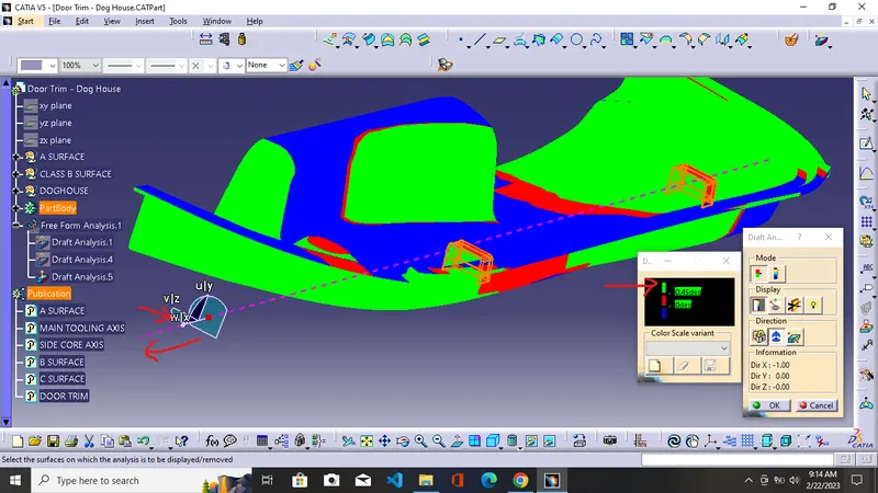
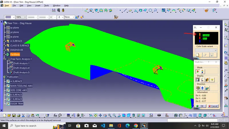
STEP 1 = Select the Feature draft analysis tool and move the compass to the tooling direction and align the compass w axis to the tooling axis. After aligning the compass with the tooling direction again click the compass tool to insure the proper alignment of the w-axis with the tooling axis. After the proper alignment uses the locking tool to lock the compass with the tooling axis.
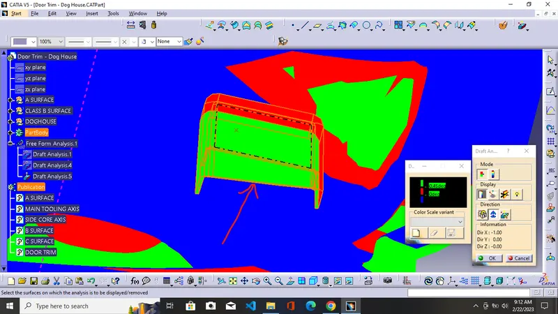
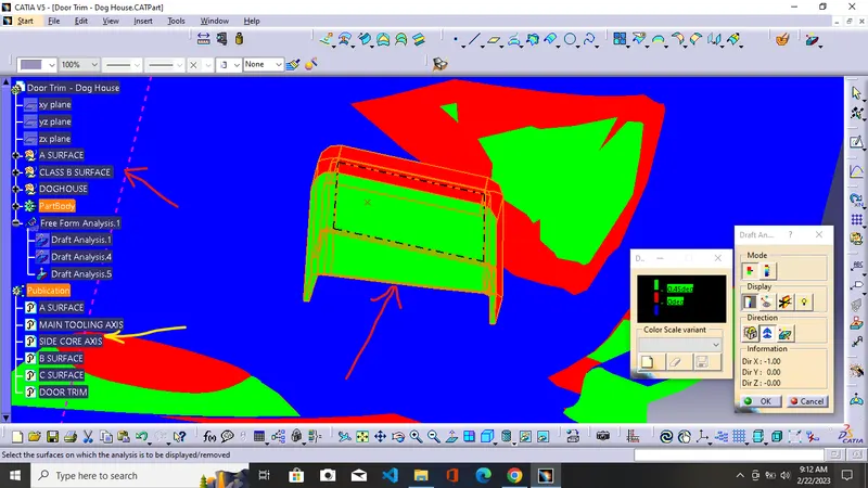
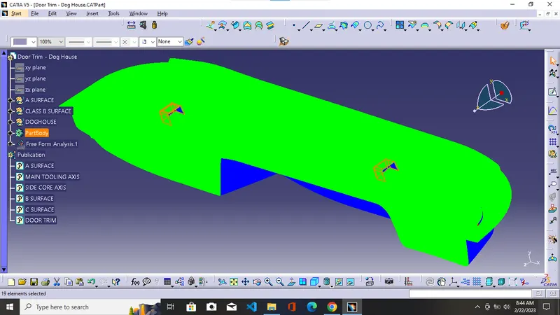
STEP 2 = Click anywhere on the A surface to generate the draft analysis report and use the quick analysis mode option to see the color code values where the green color defines the parts which have a draft angle greater than the green color code value generally it is up to 3 degrees in values. The red color gives information about the parts which have angles between 0 to up to a green color value which is generally up to degrees. The blue color gives information about parts that have an angle less than the red color. If A surface comes out in green color means our tooling axis is perfect and we are ready to go for the formation of B and C surfaces.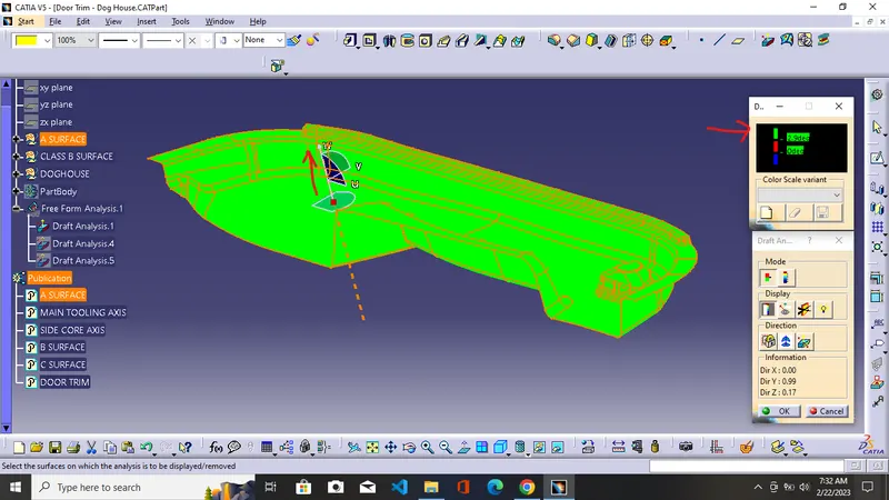
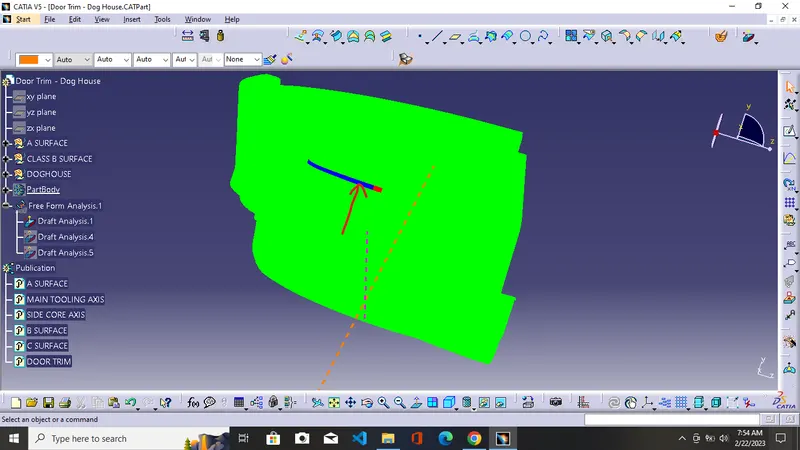
NOTE: some surface of the class A body does not clear the draft analysis test along the tooling direction as the designer does not give enough draft angle to the surface. We go with this surface as we are not allowed to modify the surface.
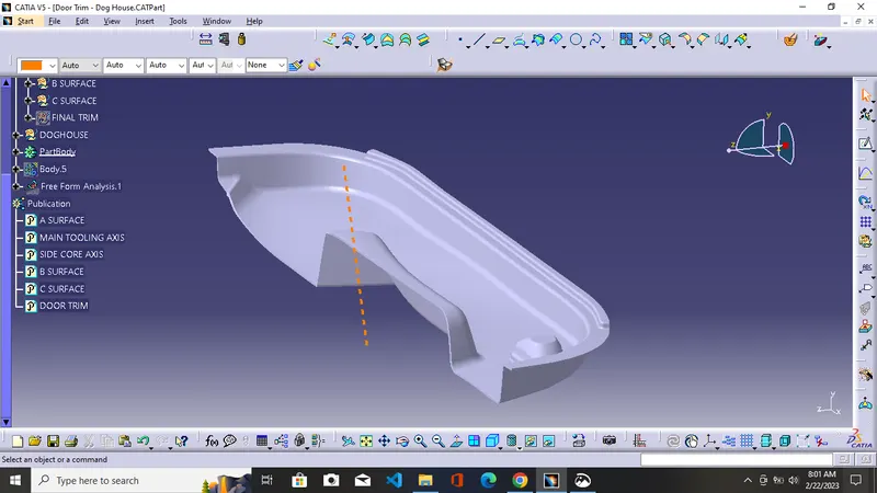
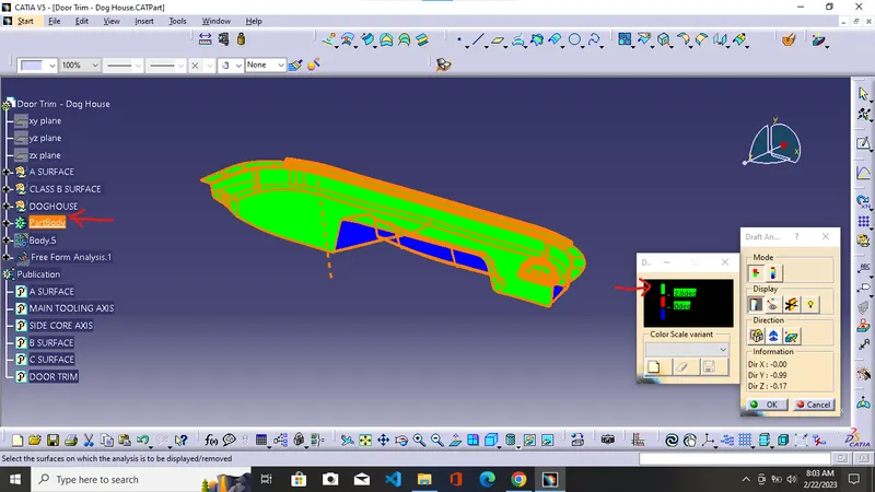
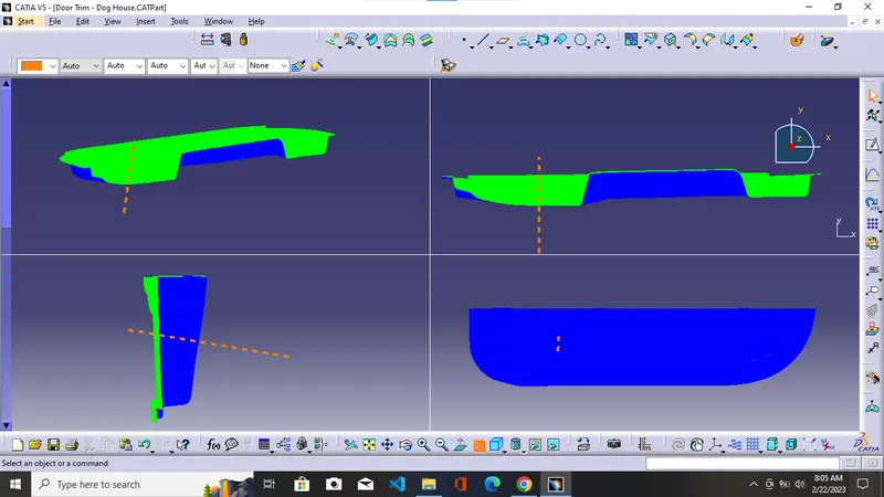
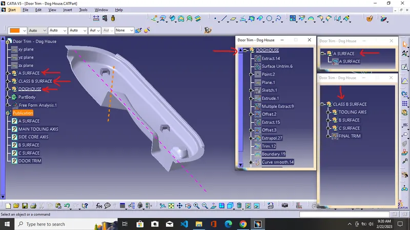
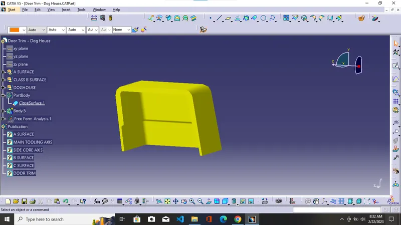
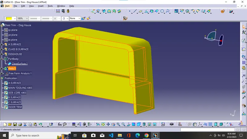
DOG HOUSE = Dog house is an engineering feature used in the plastic trim design. Dog houses are used as supporting features. It also uses when we want to use the screw boss at a large distance to prevent the buckling of the screw boss under the load and to reduce the sink marks on the surface.
DESIGN RULE OF DOG HOUSE
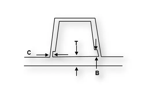
The image above gives us the empirical relationship between the component thickness and height, draft angle, and fillets for the dog house.
The image above gives us the empirical relationship between the component thickness and height, draft angle, and fillets for the screw boss creation.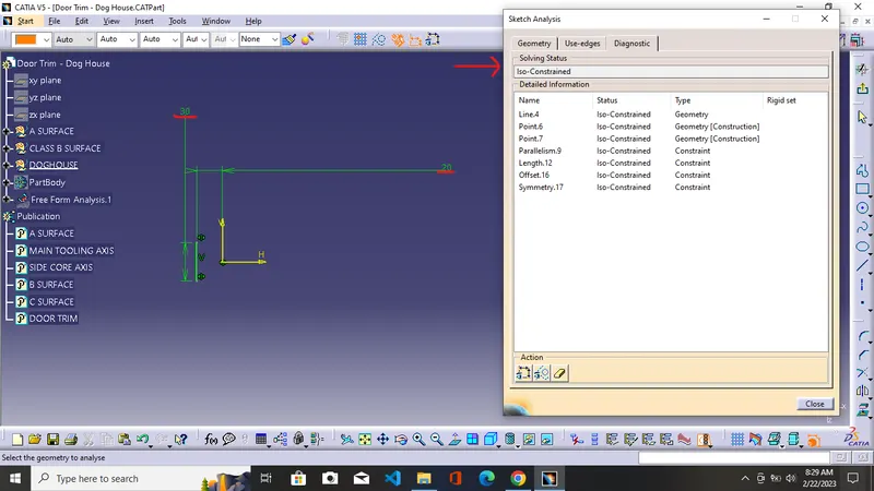
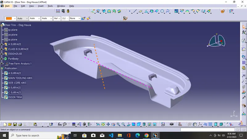
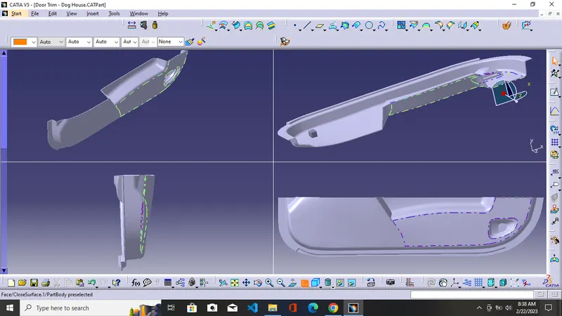
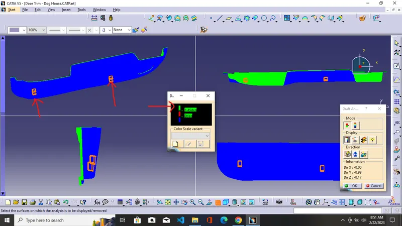
SIDE CORE AXIS = It is the other/alternate axis which uses for the draft analysis when side cores are used for the proper formation of components without affecting their useability and providing easy removal of components.
The steps are the same for the formation of the side core axis as we used in forming of main tooling axis.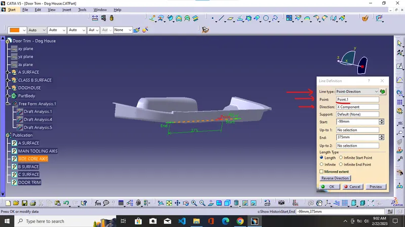
here we use point and direction in line type where the point is the old point that we made during the formation of the main tooling axis and the direction is along where we require to clear the object.