Week 9 - Attachment Feature Creation - Challenge 2
Design Report:
1. Input Surface:
The input surface which is obtained from the studio is subjected to curvature continuity and draft analysis. Based on the obtained Class A surface, it can be observed that the surface requires two boundry curves. The main tooling boundary curve and the side core boundary curve. The results obtained through the curvature and draft analysis shows that the curvature is continous and the draft angle of 3 degree is not maintained uniformly along all sides. There is no draft given for the vertical surfaces. Assuming that the A surface considerations are satisfied on experts openion, the design processes is further proceeded. The curvature continuity and draft analysis are considered as input analysis over here.
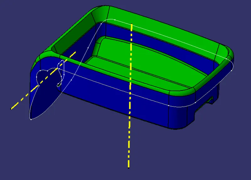
Input Analysis Of Coin Holder Class A Surface
2. Class B and C surfaces:
The B and C surfaces are formed with respect to coin holder thickness requirement, draft angle, internal and external radial requirements. While considering the C surface it is made normal to A and B surfaces since there is no draft given at any vertical wall of coin holder class A surfaces.
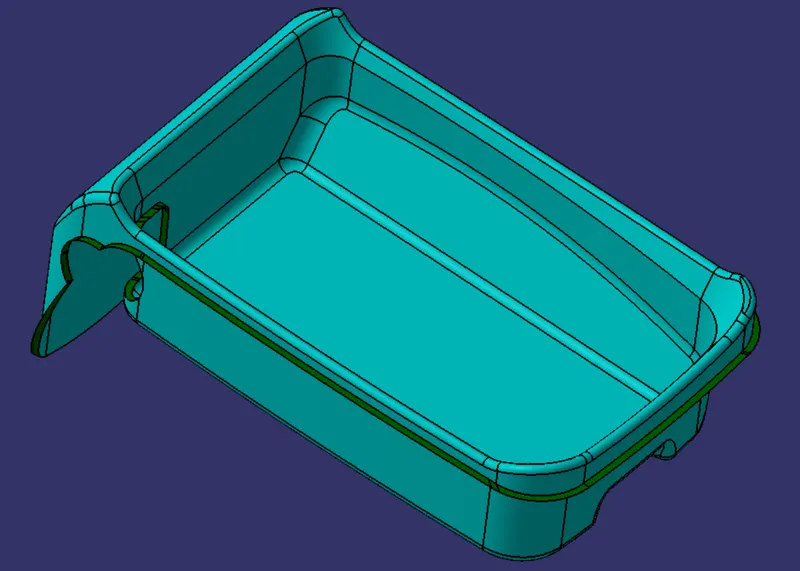
Class B and C Surfaces
3. Part Body and Draft Analysis:
Inorder to obtain a part body, it is necessary to obtain an closed loop envelop. All the 3 A,B,C surfaces are checked for closed volume visually and the surfaces are joined together. The closed loop surface is converted into part body using the closed volume tool in the part workbench. Incase if the closed volume surface is not obtained, then the surfaces are to be checked again, to obtain the closed loop.
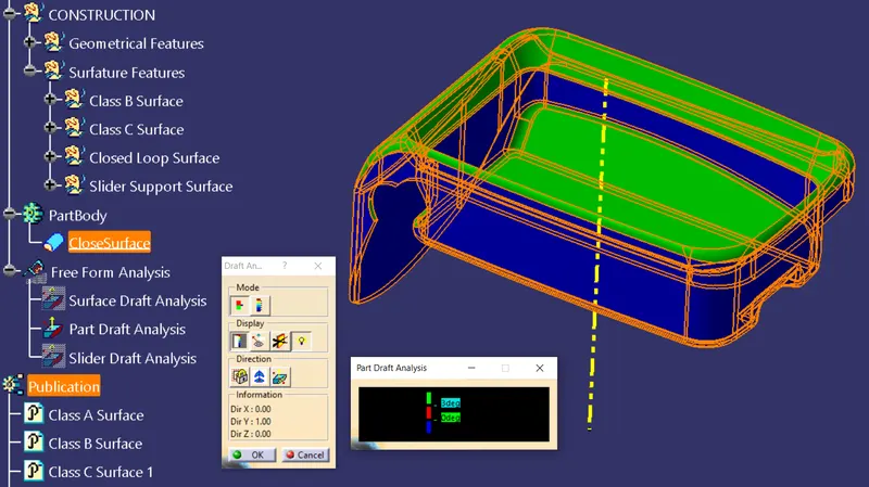
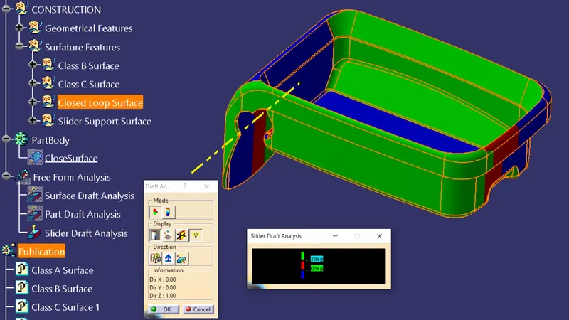
Part and Slider Draft Analysis
4. B Side Features:
The Rib, Screw boss, Dog house are the three mojor B side surfaces. The ribs are supports which are used to maintain an optimal thickness and increase strength of the product. The screw boss is the feature which is made to engage fastners to it, inorder to assemble with other plastic components. The dog house is a type of elevation on the plastic part which is set to attain better fixing position and get rid of sink marks in the A surface of the component.
5. B Side Feature Design and Draft Analysis:
The Rib is designed with 0.5 degree draft angle, 40% of the nominal wall thickness, 0.25 mm of minimum fillet radius is created over the B side area of the part body. While creating the rib, depending on the area in which the ribs are created, the deviation of design parameters are allowed up to certain extent. For instance the ribs which are held directly to B surface is maintained with 5X times the nominal part thickness, Maintaining 0.75 mm of width towards the clif of the rib. The rib root diameter of the ribs which are in direct contact with the B surface, must not be greater then 130% of the nominal wall thickness. [(2.5) ≤ (2.5 x1.3)] Here 2.5 mm is the nominal wall thickness for the coin holder. A minimum fillet radius 0.25 mm must be maintained everywhere in the part body, since it is hard to machine sharp edges at plastic production process. The ribs connected to dog house need not to be maintained at high accuracy as that of ribs in dirrect contact with the B surface.
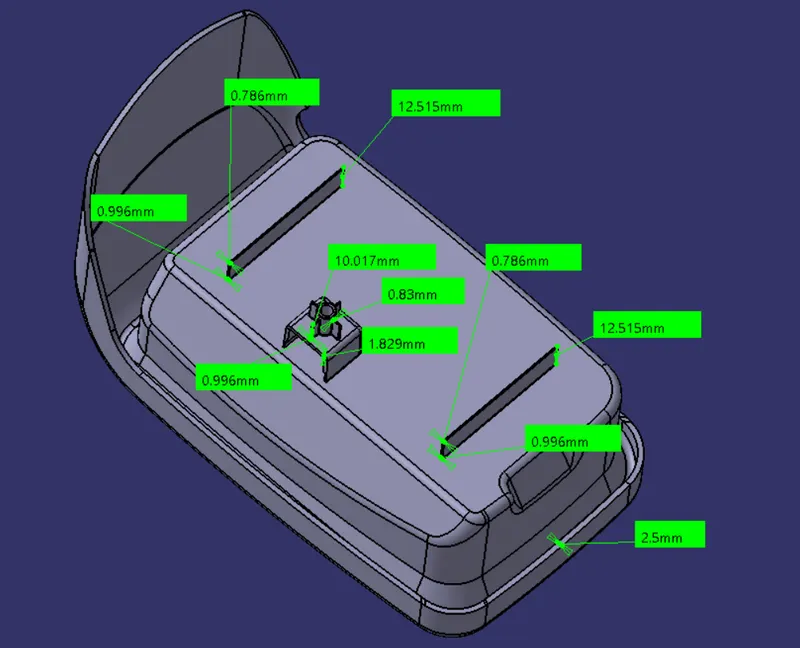
Rib Dimentional Values Consedring Design Requirement's
The Screw boss is designed for M6 screw. Having the minor diameter of 5.2mm as referance to hole in screw boss, the cylindrical wall of the screw boss is designed for 1.5 mm thickness with 0.5 degree draft. The height 12mm is given as per the prefered ratio approximately. Inorder to satisfy the root diameter of the screw bose, the internal diameter of the screw boss, which is in contact with the dog house is removed for an extent of 0.6mm with 0.5 degree draft as per the design requirement.
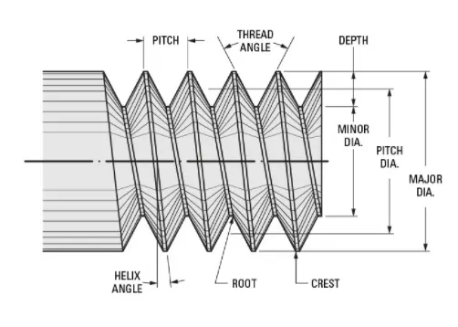
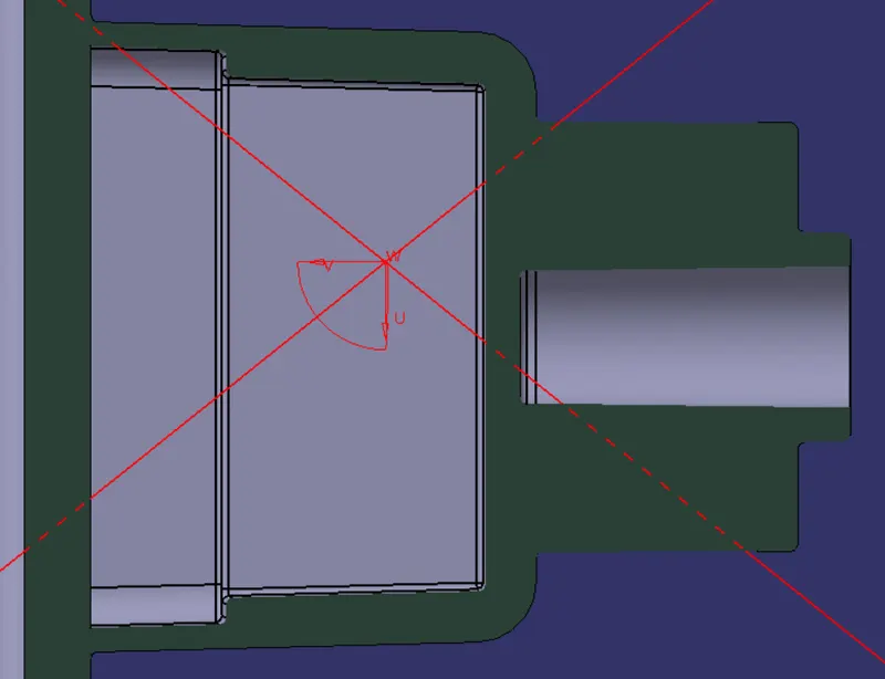
Screw Thread Nomenculature and Cross Sectional View of Screw Boss with Dog House
The complicated orentations of fixtures in parts can be managed with the dog house, doghouse is also used to avoid sink marks in class A surface. The dog house is created with the draft angle of 1.5 degrees, with prefered height to width ratio approximately. The minimum radius is kept as 0.25 mm and internal,external radius are followed as per the formulas in the design requirement. The thickess at the base of the dog house is made as 40% of the nominal thickness of the coin holder, the height of the 40% base thickness is extended upto 5mm, to avoid the sink mark. The internal area of the dog house is drafted for 0.5 degree for smooth slider movement and to avoid the damage occurings in the part.
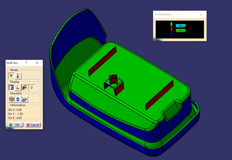
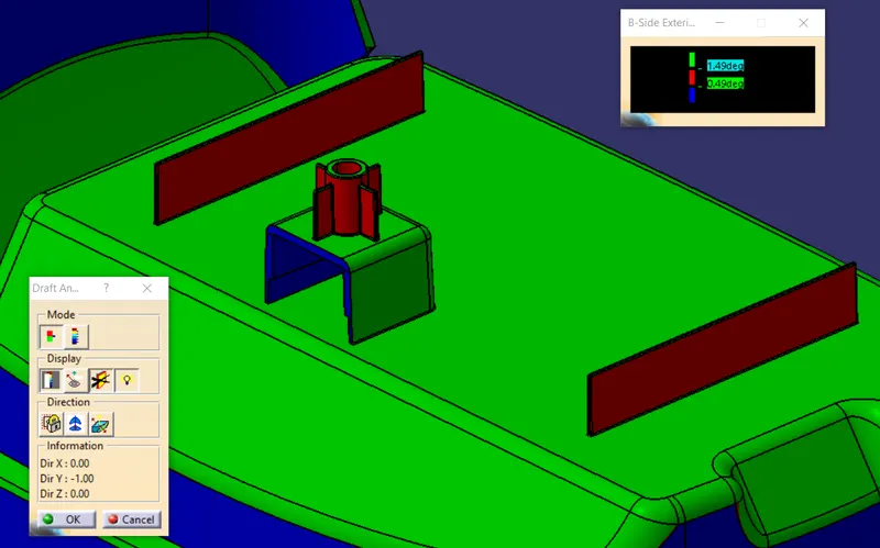
B side and B side attachment feature draft analysis
The B side draft analysis on the above left hand image shows that, there is no draft given on the vertical wall of the left side of the image. On the other hand, the left side of the image also shows that, a draft of 0.5 degree and above is provided for the ribs, screw boss and dog house. From the left hand side image, we can know that all the features which are between 0.5 to 3 degree are in red colour, but the external wall of the dog house must have a minimum draft angle of 1.5 degree. Inorder to conform the draft of 1.5 degree, another draft analysis is done with 0.5 to 1.5 degree as red colour code, 1.5 degree and above as green colour code. Another draft analysis, specificely on B side attachment feature is shown on the right hand side, it shows that the external wall of the dog house has a minimum draft of 1.5 degree and above. Thus the draft angle is provided properly to the external B side features and the processes is executed further.
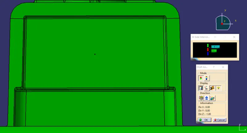
Dog House Draft Analysis
Since the draft provided at the internal wall of the dog house cannot be cleared with main tooling axis alone, an additional slider tooling axis is provided to the internal wall of the dog house and a draft of 0.5 degree and above is provided to it. The draft analysis along the slider tooling axis is done. The green colour observed on the feature of the above image shows its colour code for a draft of 0.5 degree and above. Thus proper draft is provided on the internal feature of the dog house, along the slider tooling axis for dog house. Thus the design is created with proper design requirement and the processes is further executed for future proceedings.
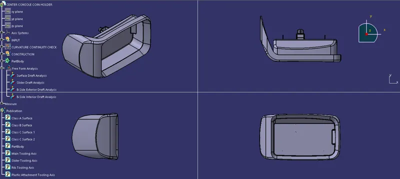
Front, Top, Side and Isometeric View of Coin Holder
The image of the complete visual representation in different views is shown above. The completed part is represented with different views to obtain an better prespective based on visual representation.