Week 9 - Attachment Feature Creation - Challenge 2
Attachment Feature Creation - Challenge 2
AIM:-
Create the Dog House for the Door Trim considering the design rules.
INTRODUCTION:-
DOG HOUSE:
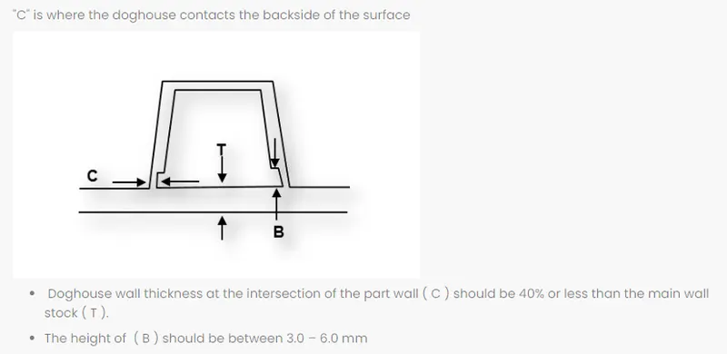
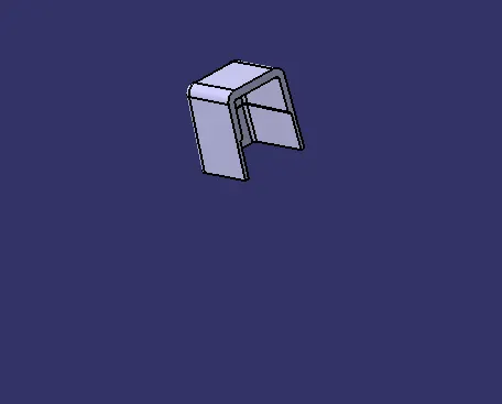
Dog house is an engineering feature used in plastic design. Dog houses are used as support feature. Sometimes other engineering features like snaps, locators, and screw bosses are mounted on them to increase their strength.
Dog houses are subjected to draft analysis to prevent breakage of the component during ejection from the mould cavity. Dog house and other engineering components are built on the B-surface.
OBJECTIVE:-
- Create a Tooling axis for the given CLASS -A surface.
- Create the CLASS B and C surfaces of door trim using the given CLASS-A surface.
- Create a final surface model and convert it into a solid body using the close surface command in the part design workbench.
- Crea ate side core axis for the dog house
- Create Dog house on the B surface by considering the design rules.
- Perform draft analysis for both Class-A surface and Final part body.
Design Methodology:-
Class-A surface means visible surface. It gives the aesthetic of the component which is created by the styling team and gives to the part design engineer to create the part with all engineering aspects.
Given class A surface:-
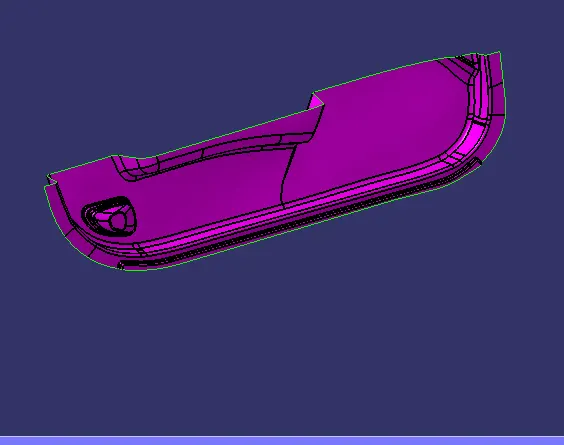
Check for continuity of the given surface using Join or Boundary commands.
If there are no gaps on the A surface, create tooling axis.
TOOLING AXIS:-
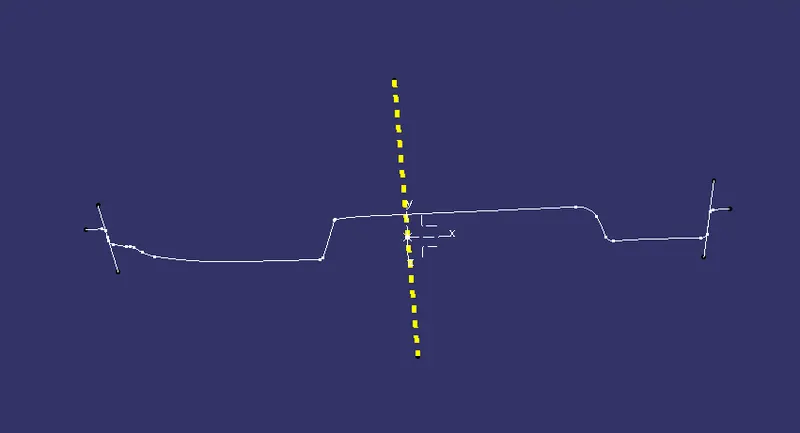
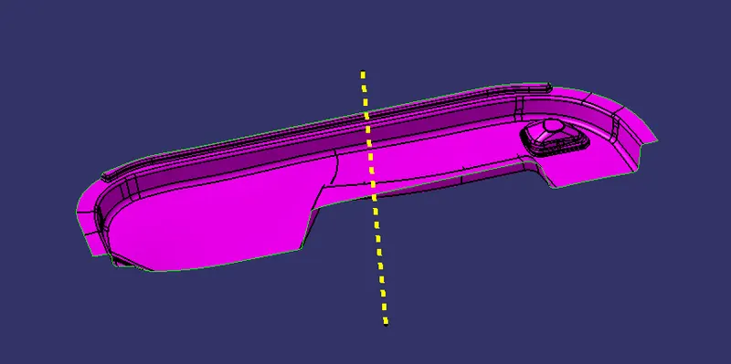
- The next step is to create the tooling axis for the part which will determine the direction in which the core and cavity of the mould will move.
- Designer must ensure that all holes and slots are covered in the main tooling and thus side core must be avoided whenever possible.
- After analysing visually for the best possible tooling axis, an axis system is created on the centre of one of the surfaces of the door trim.
- The main tooling axis is created normal to the y direction.
Draft Analysis:-
The Draft Analysis command enables you to detect if the part you drafted will be easily removed. This type of analysis is performed based on color ranges identifying zones on the analyzed element where the deviation from the draft direction at any point, corresponds to specified values.
- Before going to drat analysis go to customized view parameter >under mesh >check material and then click ok.
- Now for draft analyses go to insert » analysis » feature draft analysis.
- Use the compasss to define the draft direction.
- In the colour scale change the draft angle to 3 degree.
- The component changes to green in indication of passing draft angle.
- Use running point to check the angle on the component.
CLASS-B Surface Creation:-
Class-B surface means the thickness of a part it is not visible and is inside part. In other words, the Class-B surface is a surface below a certain thickness from the class-A surface. This is the surface that contains engineering aspects of a model.
- Crean ate offset surface of Cin LASS-A about 2.5mm inward direction.
- Check for discontinuity and rework on the offset surface using extract, multi-extract, multi sections surfaces.
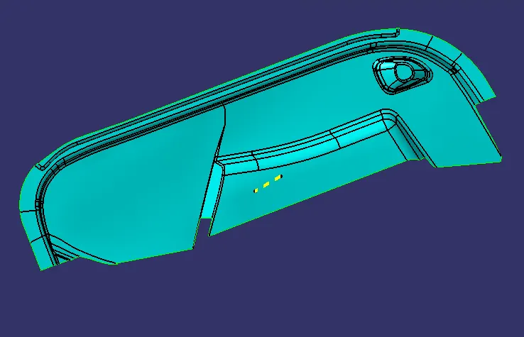
- Extract the surfaces from the class A using multiple extract and untrim them.
- Use Extrapolate to make sure that all the untrims are properly intersected to trim and offset the surfaces to 2.5 mm to create the thickness.
- Trim the extra surfaces using trim command.
- Insert them into new geometrical set and name it with respective part names.
- Apply fillets to the model after creating the entire surface.
- If the edges are outside the fillet value will be added to the thickness of the component and if the edges are inside, the fillet value will be subtracted from the thickness of the component, for instance the thickness of the component Is 2.5mm the fillet value is 15mm so the outside portion value should be 17.5mm and inner eges should be filleted 12.5mm to get uniform thickness.
- Perform trims one at a time so that it will be clear to understand.
CLASS-C Surface Creation:-
The surface that joins class-A and class-B surfaarethe s is class-C surface. Class C is often specified for interior surfaces not readily visible, surfaces that will be covered by another part when assembled
- Create the sweep concerningerence to the surface and tooling axismulti-extractingting the CLASS-A boundary
- Join the sweep surfaces by using commands like extrapolate, trmulti-sectiontion surface.
- Finally join all the sweep surfaces and ensure the continuity of the CLASS-C surface.
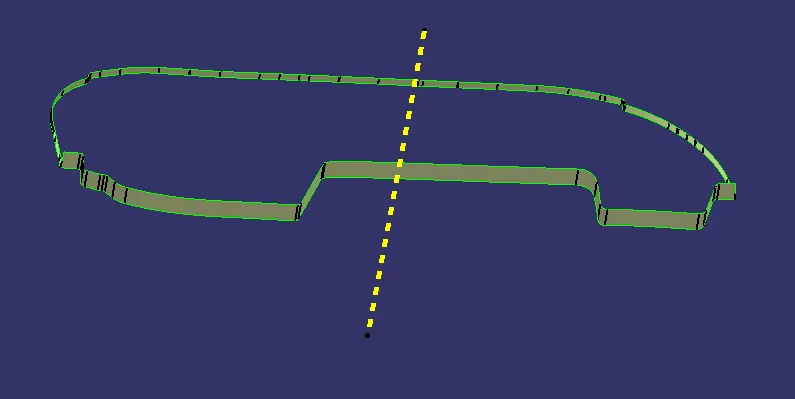
Class A&C Surface:-
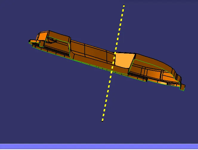
After getting sweep then trim the output with class B surface to get final output.
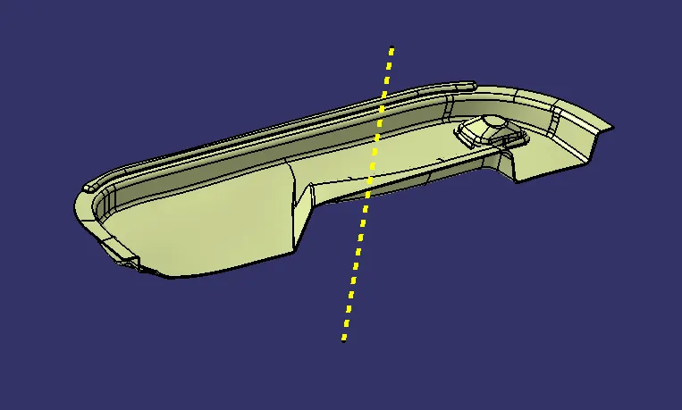
Now open part design workbench and using close body surface create a solid of the component.
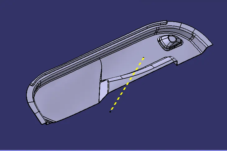
B SIDE FEATURES CREATION
DOG HOUSE CREATION
- Design Principle for Dog House Creation
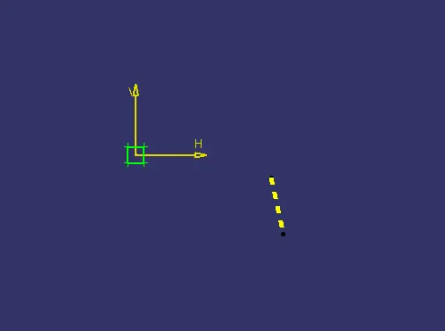
Sketch Used For Dog House creation:-
DOG HOUSE:-
Side core Draft Analysis Of Dog House:-
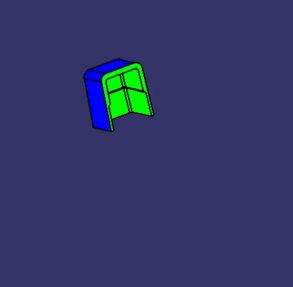
Final Draft Analysis Of Dog House:-
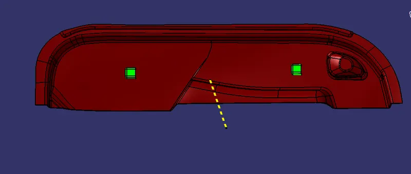
Isometric View:-
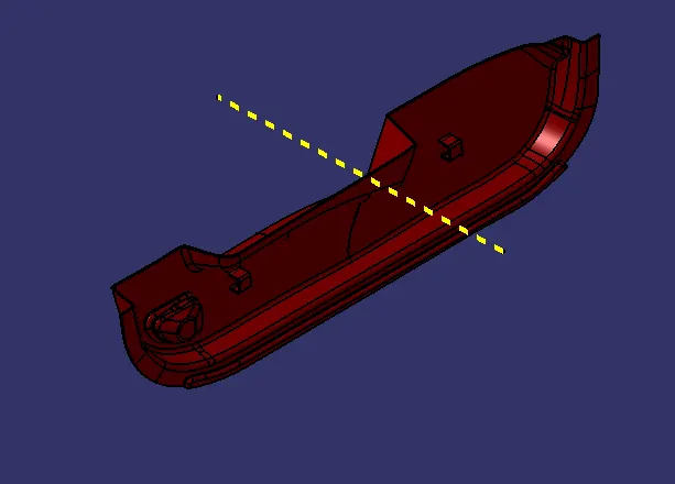
Top View:-
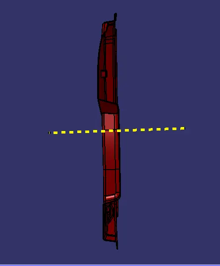
Front View:-
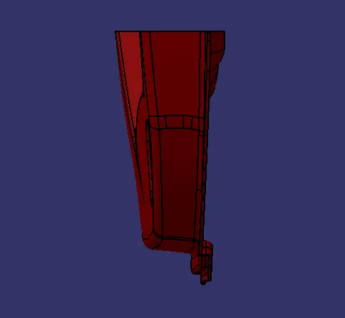
Side View:-
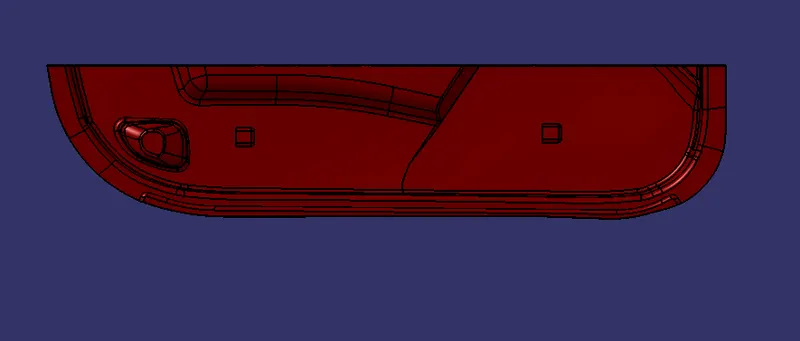
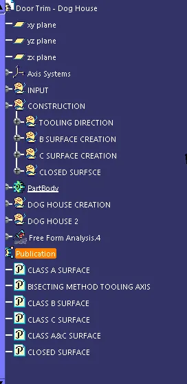
Tree Structure:-