Week 9 - Attachment Feature Creation - Challenge 2
CREATE THE BOSS AND DOG HOUSE FOR THE CENTER CONSOLE COIN HOLDER
OBJECTIVE –
To create Screw Boss and Dog House on Coin Holder Based on the Design Consideration Using CATIA.
SCREW BOSS CREATION –
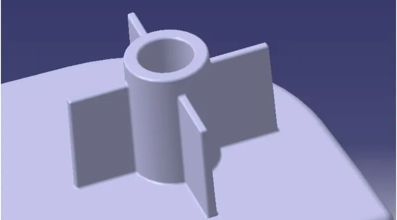
Boss feature is commonly found in injection moulding designs. They are used to aid in the assembly of moulded parts by providing a channel for a screw. Designing plastic screw bosses is fairly straightforward, but there are a few considerations to ensure a strong connection between parts and mitigate cosmetic defects.
Design Criteria –
SCREWBOSS CREATION IN CATIA -
First, create two circles in the sketch.
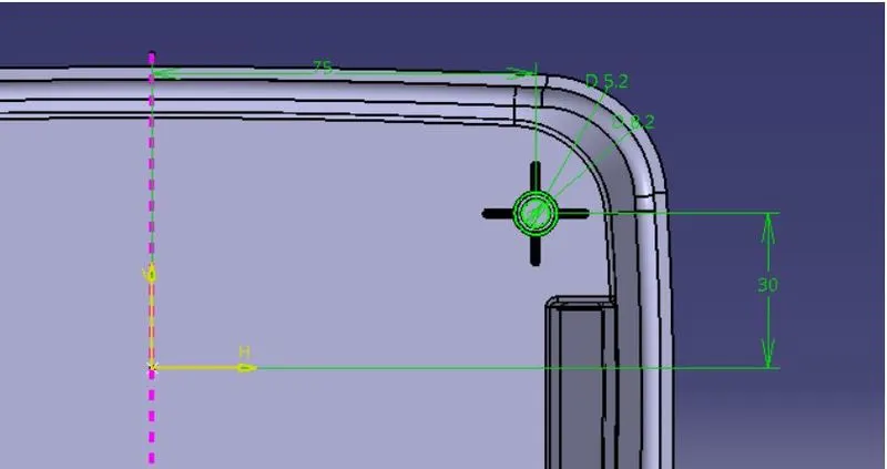
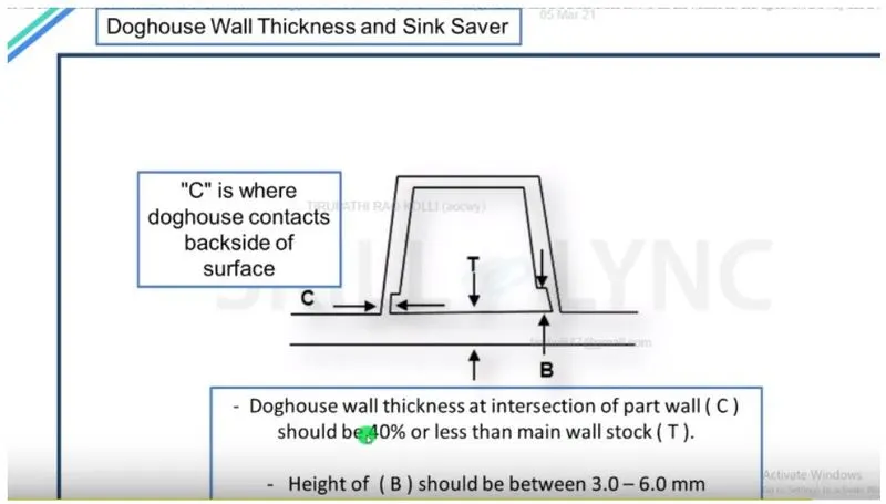
The inner-circle diameter is 5.2 mm and the outer circle diameter as per design criteria.The thickness of the Screw boss should not be higher than 40% of the bass.
The thickness of Coin Holder -2.5 mm
The diameter of the outer circle is -7.2mm
As per the given parameters, the draft angle and fillets are provided.
Dog house creation –
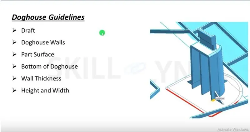
The dog house is an engineering feature used in the plastic trim design. Doghouse is used as a supporting features. Sometimes other engineering feature like snaps, locators etc..are mounted on them to increase their strength. The dog house is subjected to draft analysis to prevent breakage of the component during ejection from the mould cavity. Dog house and other engineering components are built on B-Surface.
DOG HOUSE CREATION –
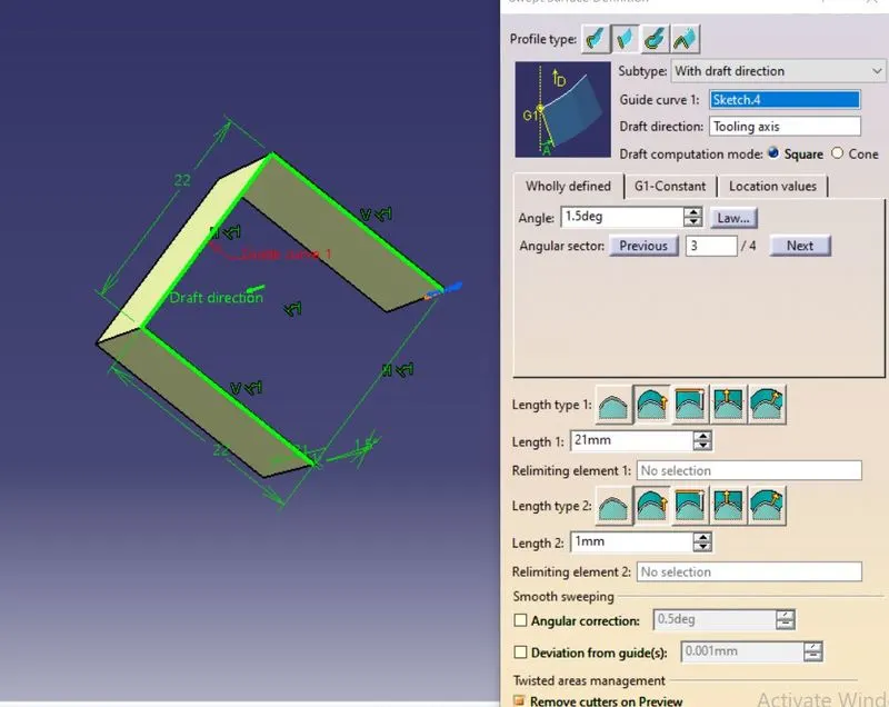
First, create a rectangular sketch (one end made as construction )
Next used to sweep command with draft angle 1.5 degree and height 12 mm
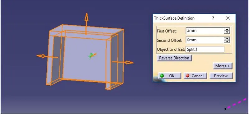
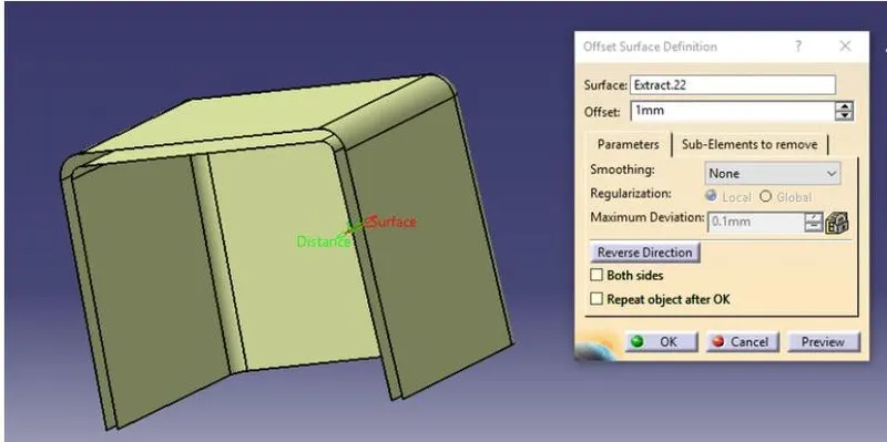
To adjust the height and bring it perfect dog house shape I used the command Surface Untrim, Offset and trim.
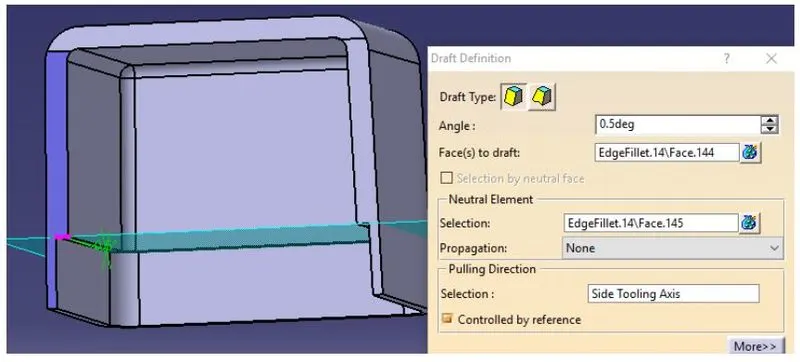
The draft angle of the inner side of a dog house is 0.5 degree.
The edge fillet of the inner side of the dog house is given a nominal diameter of 1mm.
The height of the dog house is given as 5mm whereas given design parameters is was indicated between 3-6 mm.
Draft Analysis
The purpose to perform the draft analysis on the component is to check the eligibility of the component in the manufacturing process of the plastic moulding. By performing draft analysis on the component we can check the draft angle of the component which generally is 3 degrees, the draft angle helps to easily remove the component from the mould in the core and cavity in the manufacturing process.
The process to perform the draft analysis on the component is:
- First, Go to Insert>Feature>Insert feature draft analysis
- Then position the compass on the axis line we created.
- Then select the surface.
- Then use the Analyse under running point to check the draft angle of the surface.
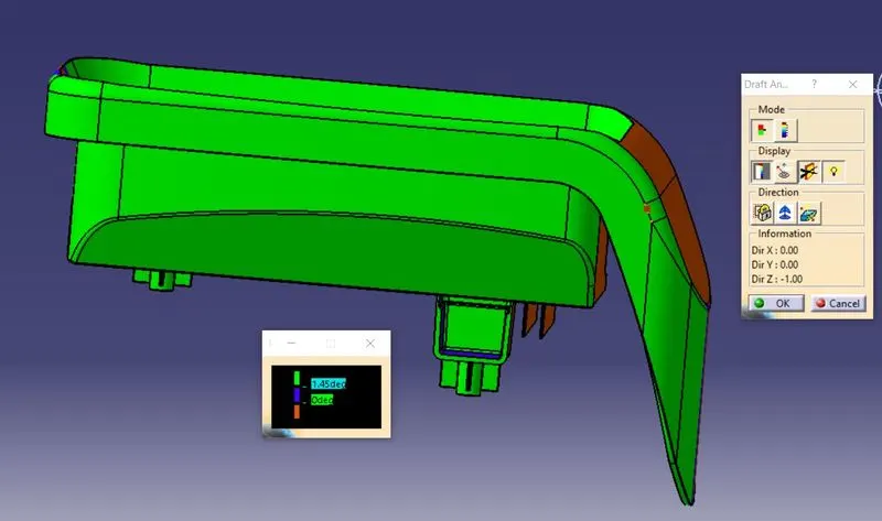
ISOMETRIC VIEW
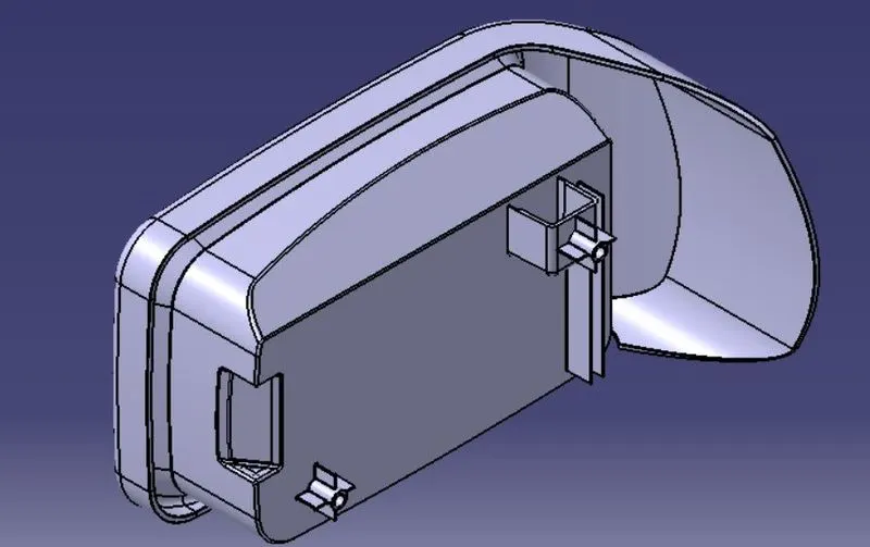
FRONT VIEW
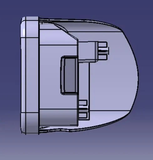
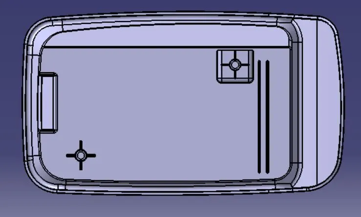
TOP VIEW
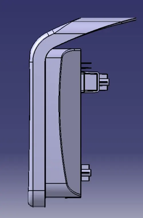
SIDE VIEW
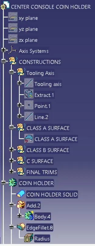
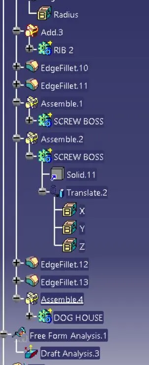
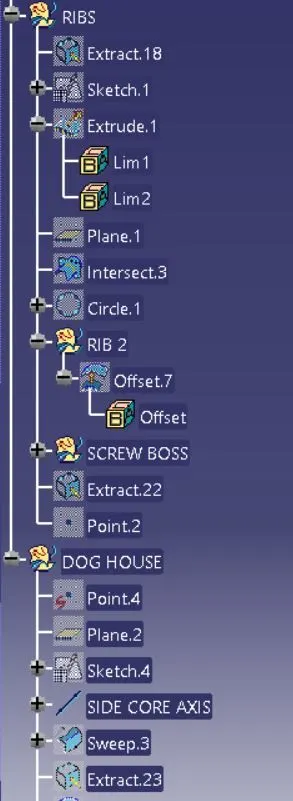
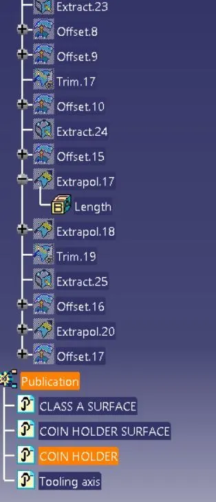
TREE STRUCTURE