Week 9 - Attachment Feature Creation - Challenge 1
DESIGN AND DRAFT ANALYSIS OF RIB IN COIN HOLDER
AIM
To design the rib on the B-side of the coin holder according to the plastic design rules, and to perform draft analysis on that rib.
PROCEDURE
Before designing the rib, we need to know about the rib. Rib is a B-side feature which is used to increase the strength of the component in an economical way, that means we can increase the strength of the component without adding thickness by adding ribs to it.
Nowadays ribs are not only used for strengthening purpose but also for
- locating and arresting components in assembly
- Providing alignment in mating parts
- Acting as stops or guide for mechanism.
There are some design considerations while designing a Rib
- Thickness
- Height
- Location
- Quantity
- Manufacturing
These are the major considerations we have to consider while designing a rib.
Now we will see the design procedure of the rib, first we have to select the base of the coin holder area and extract, then use the positioned sketch option to create the line and make it as an output to extrude the line easily,
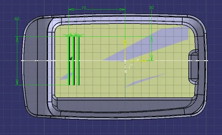
and extrude height should be calculated as per the rib calculation formula.
The height of the rib should be always 5 times the wall thickness of the component(5*T) here T- represents the thickness of the part.
So the height of the rib should be 5*2.5=12.5mm.
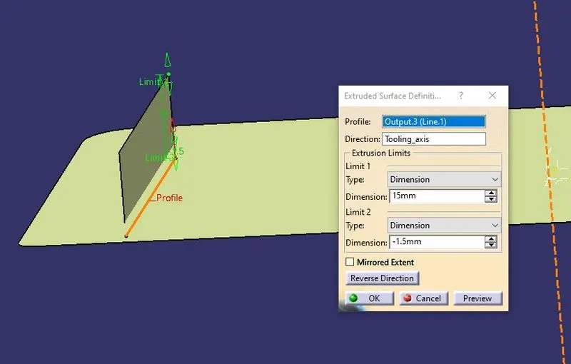
Here the height of the extrude is given as 15mm that is because the sketch plane lies on the A-surface side which is 2.5mm apart from the B-surface side.
Then we have to use thick surface command in the part work bench to add the thickness to the surface extruded, and the thickness value is calculated according to the formula
Thickness of the rib =0.4 times the wall thickness of the part (0.4*T).
Thickness of the rib is (0.4*2.5) = 1mm
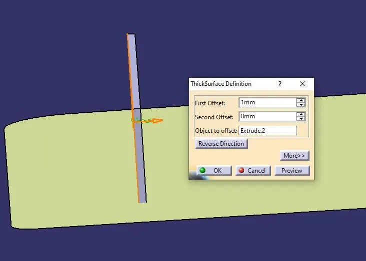
After giving the thickness to the rib then we have to add the draft values to the rib, this draft will help in easy ejection of the part from the mould and avoid part and mould’s wear and tear.
This draft value also has a calculation to ensure the cavity for the draft can be manufactured. The minimal draft value of 0.5 degree per side should be given to the ribs, but always ensure that there is minimum of 0.75mm thickness should be there in the edge of the rib area, then only the mould and cavity area of the rib gets filled easily.
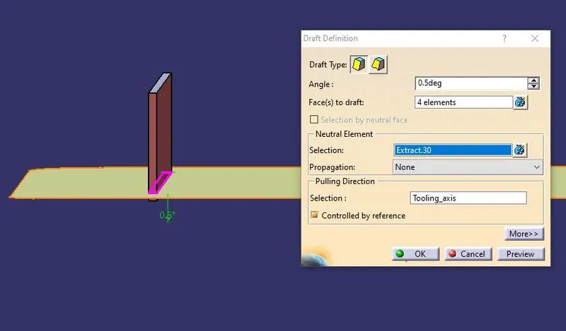
Select the draft command and select the faces to draft and select the extract as a neutral element and select the tooling axis as pulling direction as shown in the above image.
Then we have to give the fillet to all sides of the rib to avoid the sharp edges on the part produced, so we have to follow the same rule for giving fillet if we give excess fillet then the area of the rib attached to the part will get thicker and it will trap over heat and will tends to sink marks and other defects.
select the faces of the rib and use the fillet command as shown in the below image and the nominal fillet value should be 0.25mm
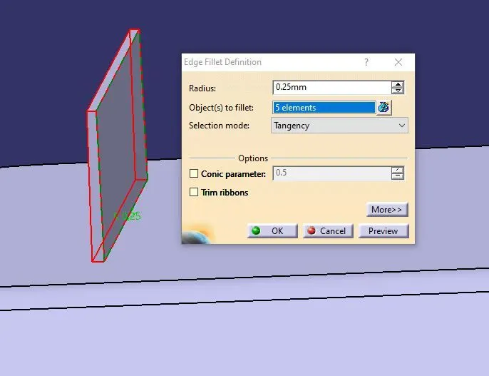
The ideal radius for the rib area is 0.25mm for all edges of the rib.
Next we have to create the another rib and here we have to take care that the minimum distance between two ribs. Always the distance should be in the ratio of 2:1 of the height to gap between two ribs, and the ratio of 3:1 is also accepted.
So the next rib distance can be found by (height/width=3:1), 12.5 is the height of the rib and width refers the gap between the two ribs and the ratio is 3, so the distance is (12.5/3) = 4.16, and make sure that we have to add the thickness of the rib value to this value then only the gap between two ribs will be as per the calculations. It is shown in the below image
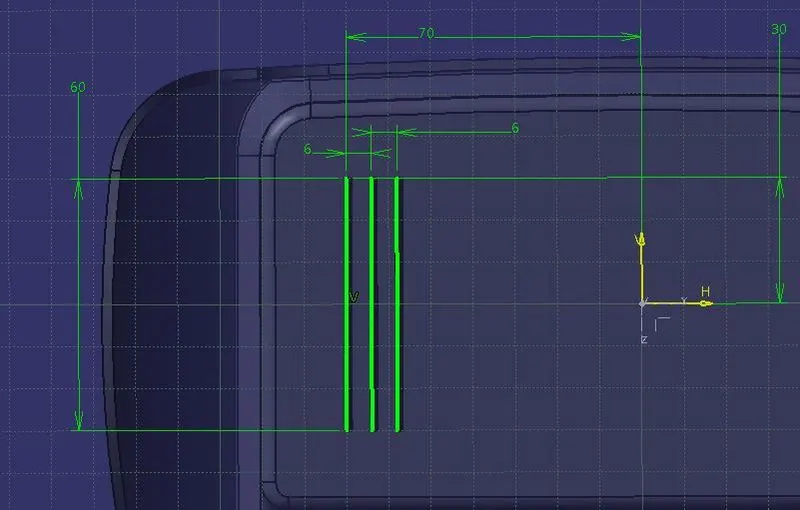
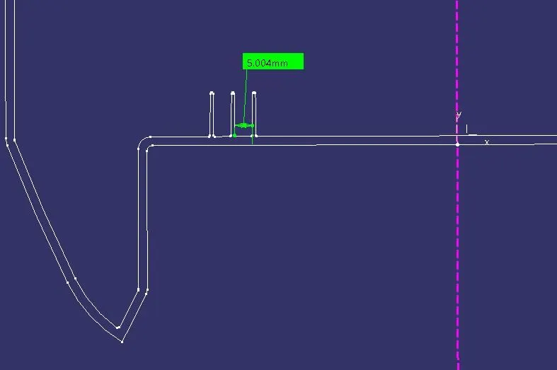
By creating a inter-section we can check if we are designing the part according to the plastic product design rules or not, and we can check the root thickness of the rib with the created section view only.
For creating inter-section we have to intersect the plane with the part we designed, and we have to create a tri-tangent circle and to measure it according to the below shown image and use the extract options to select the edges of the fillet.
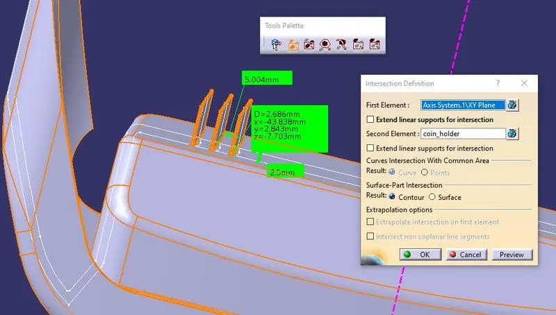
Then we have to create the circle on the reference element and select the circle type as tri-tangent then create the circle to measure the root thickness area.
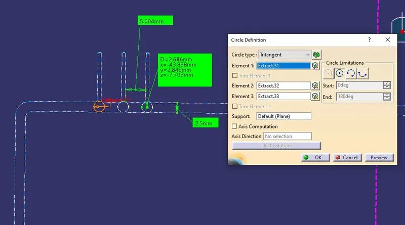
In the above image it is shown that the diameter of the tri-tangent circle is measured as 2.686mm and this is the root thickness of the rib we have designed, this root thickness of the rib can by the following formula
The root thickness of the rib should be maximum of 1.3 times wall thickness of the component, here wall thickness of the component is 2.5mm and the calculated root thickness is 2.5*1.3=3.5mm so our root thickness value is less than the calculated value it is 2.686mm so it is verified if we have a root thickness value higher than the calculated value then sink mark defect will occur.
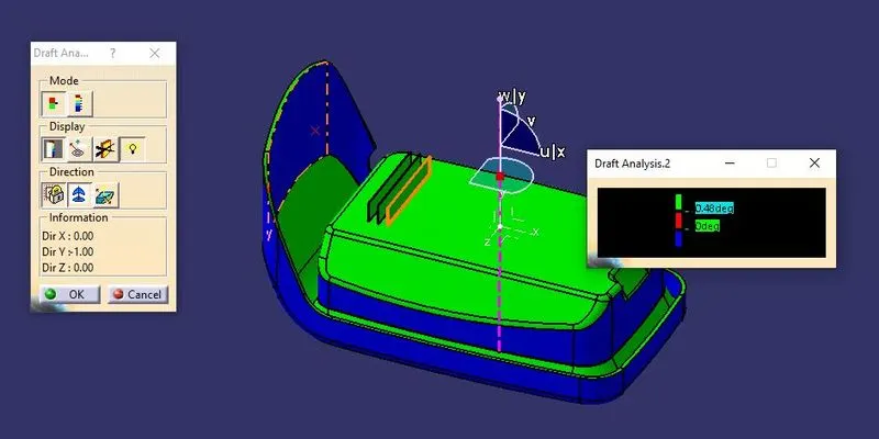
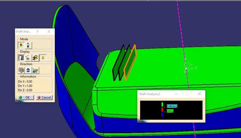
Then we have to perform the draft analysis on the created rib according to the tooling axis, and put the material mode and pick the compass and place it on the tooling axis and put the maximum value of the draft angle in 0.48degrees then we can see that the area shown in the green are cleared according to that tooling axis on the rib area, it is also shown in the below image
CONCLUSION
Thus the rib is designed according to the plastic design rules and draft analysis is also performed on that rib.