Week 9 - Attachment Feature Creation - Challenge 1
Aim:Create the rib for the Centre console coin holder considering the design rules.
PROCEDURE:
TOOLING AXIS:
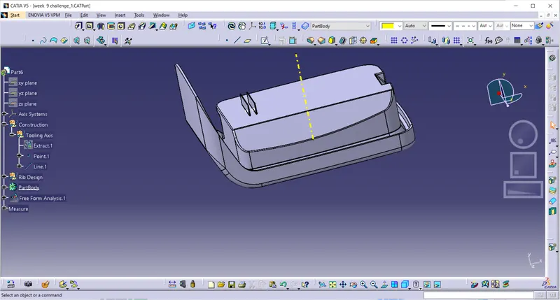
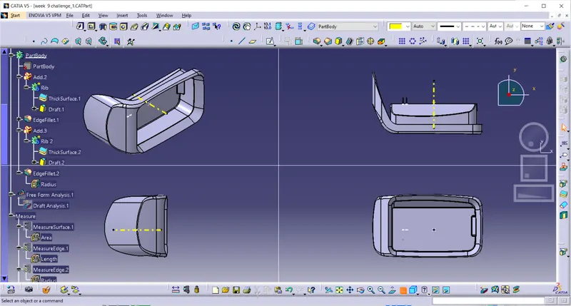
- After analysing the component, the component features seems to be clearing the tooling in Z-axis(perpendicular to base).
- Usually, a perpendicular axis to large flat surface or hole is considered as a tooling axis.
- Extract the base and create a line with point and direction perpendicular to the base.
PROCEDURE:
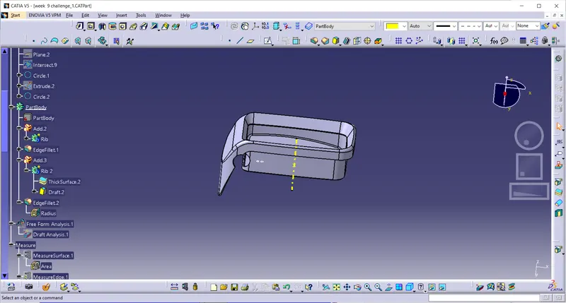
- Draw a line on the base surface of the coin holder with using portion sketch.
- Construct the line with using axis. and extrude the this line and add thicknig for this surface.
- add thickness of the rib 0.4*thickness of the component
- Coin holder thickness is 2.5mm. so consider the rib thickness is 0.4x2.5 = 1mm
- Give the draft angle is 0.5 degrees for the rib.
- Give fillet of 0.25mm. Maximum fillet radius must be 0.25mm.
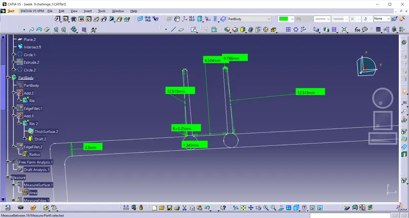
- Then translate this rib. The spacing guideline is such that the Hight/Width ratio should be maximum of 3:1, 2:1 is preferred.
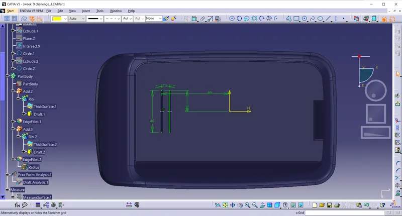
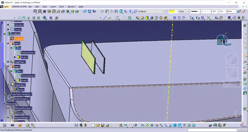
below figure we can see the measurements of the ribs satisfying the design rules.
Draft Analysis for the Rib:
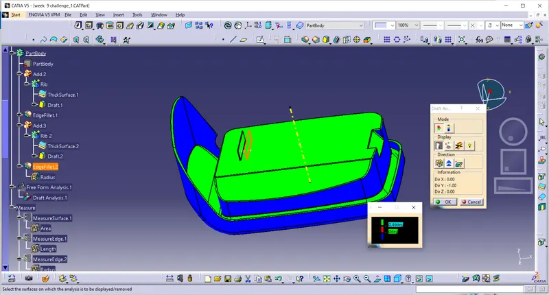
- Draft Analysis of the coin holder with ribs attached.
- In below figure we can see the 0.5 degree draft on the rib face.
- The green surfaces are having draft angle of more than 3 degrees and they can clear the tooling direction.
- The red surfaces are having draft angle more than 0 degrees and less than 3 degrees.
- The blue surfaces are having negative draft angle. As the Class A surface is not manufacturable, the same problem can be seen in the solid part. The Class A surface has to be modified and the walls should have some positive draft angle.
Orientation:
Tree Structure: