Week 9 - Attachment Feature Creation - Challenge 1
AIM:
To create ribs for the given Centre console coin holder by following the design rules.
CREATION OF TOOLING AXIS:
Step 1: Extract the top surface of the coin holder which represents the class A surface.
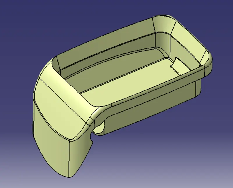
Step 2: Check the boundary of the class A surface and ensure there is no gap in between the surface.
Step 3: Create an axis system on the class A surface by creating a point on it.
Step 4: Draw a sketch by intersecting class A surface with YZ plane.
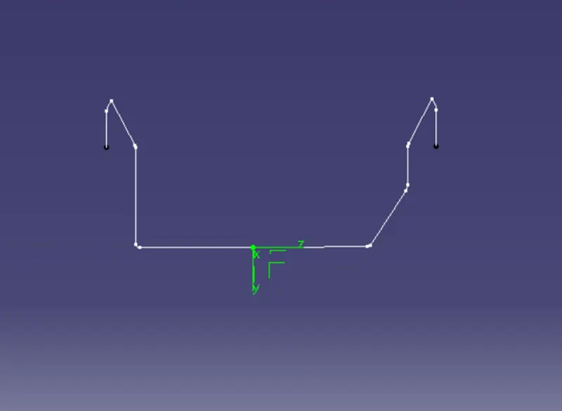
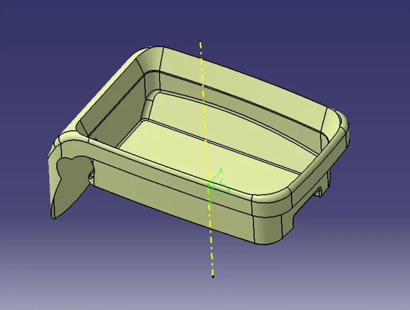
Step 5: Since the edges are parallel to the YZ plane, a perpendicular line is drawn to the base surface and it is taken as tooling axis.
DRAFT ANALYSIS ON CLASS A SURFACE:
Step 1: Change the view to customized view and enable the material in shading option.
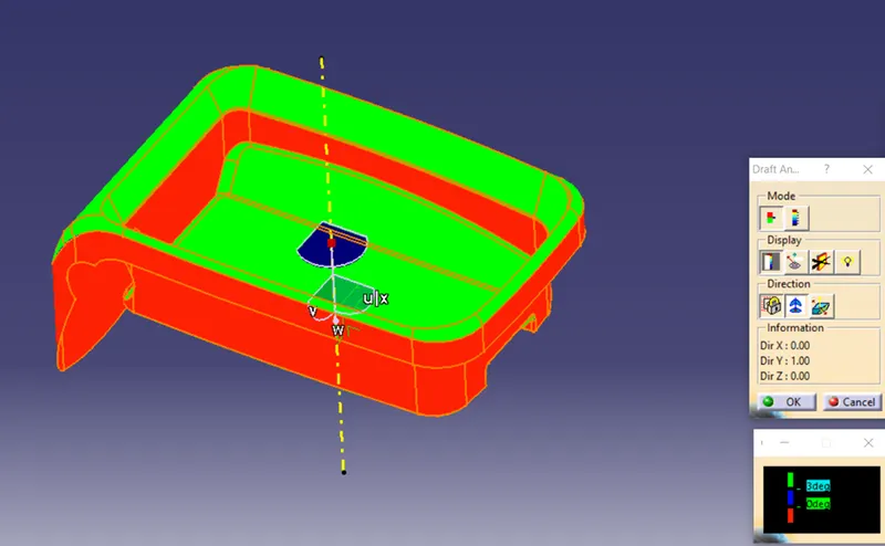
Step 2: Insert the feature draft analysis.
Step 3: Click the compass icon and place the compass along the tooling direction.
Step 4: Lock the draft direction and select the component to draft.
Step 5: Enable the color scale and change the draft value as required. Here 3 degree is given as draft angle.
Step 6: The green color indicates that the surface is more than 3 degree from the tooling direction. The blue color indicates that the surface is 0 to 3 degree from tooling direction. Red color indicates that the surface is less than 0 degree from tooling direction which indicates the negative draft.
DESIGN RULES FOR RIB:
Consider ‘t’ as the wall thickness of the component.
- Draft - 0.5 degree per side minimum
- Rib thickness, w = 0.4 * t (resin dependent factor)
- Rib thickness at the tip – 0.75mm minimum
- Rib fillet radius - 0.25mm maximum
- Rib height – 5 x t
- Height/width – 3:1 steel
2:1 preferred
RIB DESIGN:
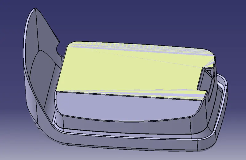
Step 1: Extract the bottom surface of the coin holder on which the ribs are going to be created.
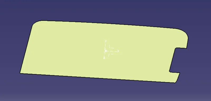
Step 2: Create a point in the middle of the surface and insert an axis system at that point.
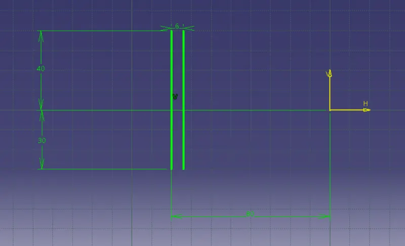
Step 3: Create a sketch on ZX plane by drawing lines (ribs) as required. The height of the ribs and spacing between the ribs should be in the ratio of 3:1 (steel height/width ratio maximum). So, the distance between the lines should satisfy this condition after thickening ribs. Here,
Y/X < 3
12.5/X < 3
X = 12.5/3
X = 4.2
So, spacing between the ribs should be greater than or equal to 4.2mm.
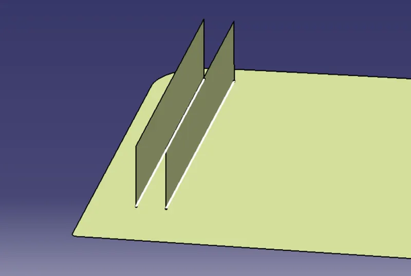
Step 4: Extrude the lines to a height of 12.5mm as the wall thickness of the component is 2.5mm, along the tooling direction.
Y = 0.5 x t
Y = 0.5x 2.5
Y = 12.5mm
Step 5: Thicken the extruded surface to 1mm.
w = 0.4 x t
w = 0.4 x 2.5
w = 1mm
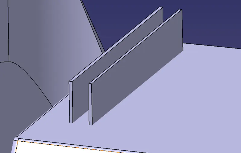
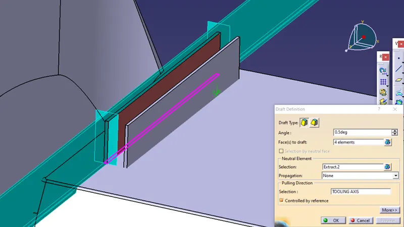
Step 6: Provide draft to the sides of the ribs for 0.5 degree along the tooling direction.
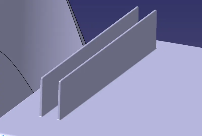
Step 7: Assemble these ribs to the main body and give fillets for 0.25mm to all edges of the ribs.
Step 8: Create an intersect between XY plane and the component.
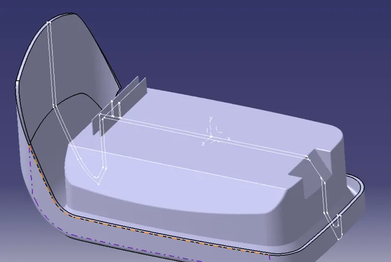
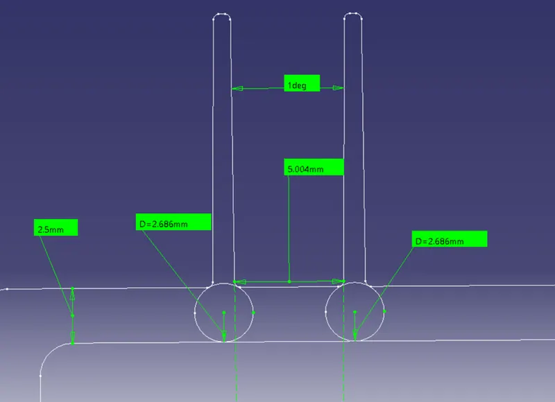
Step 9: Draw tri-tangent circles at the bottom of the ribs as shown in figure and measure the diameter of the circles. It should not exceed ± 30% of the wall thickness. In this design, the diameter should be 1.75mm – 3.25mm.
DRAFT ANALYSIS ON THE COMPONENT:
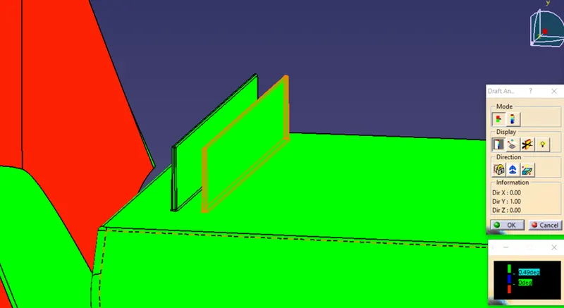
Finally draft analysis is performed on the component along the tooling axis by following the above steps.
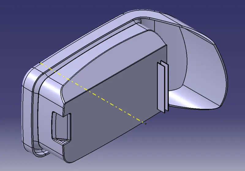
ISOMETRIC VIEW:
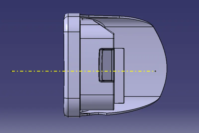
FRONT VIEW:
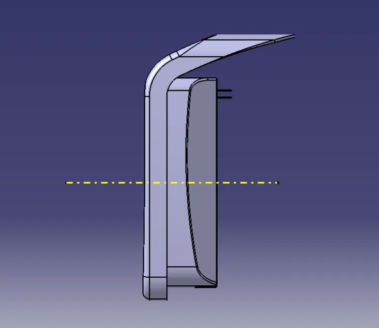
SIDE VIEW:
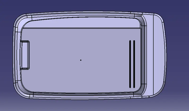
TOP VIEW:
RESULT:
Thus, ribs are created on the given Centre console coin holder and draft analysis is performed on it.