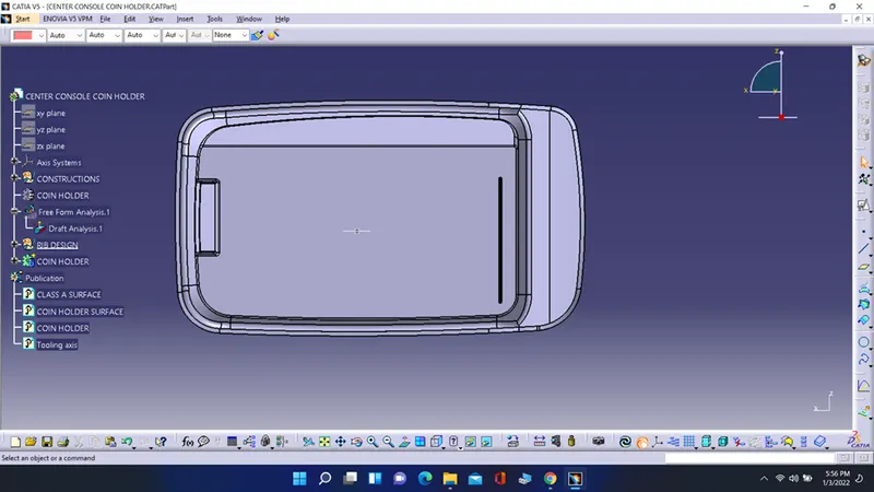
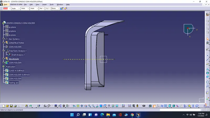
Week 9 - Attachment Feature Creation - Challenge 1
Report on the coin holder.
1. Surface draft analysis: -
- In first step we have to check the connectivity of the class-A surface. It means there should be no present gaps between two surfaces. It is fully connected class-A surface.
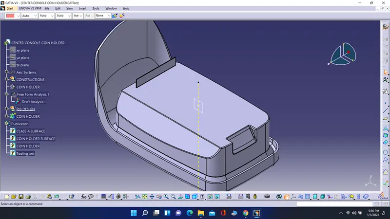
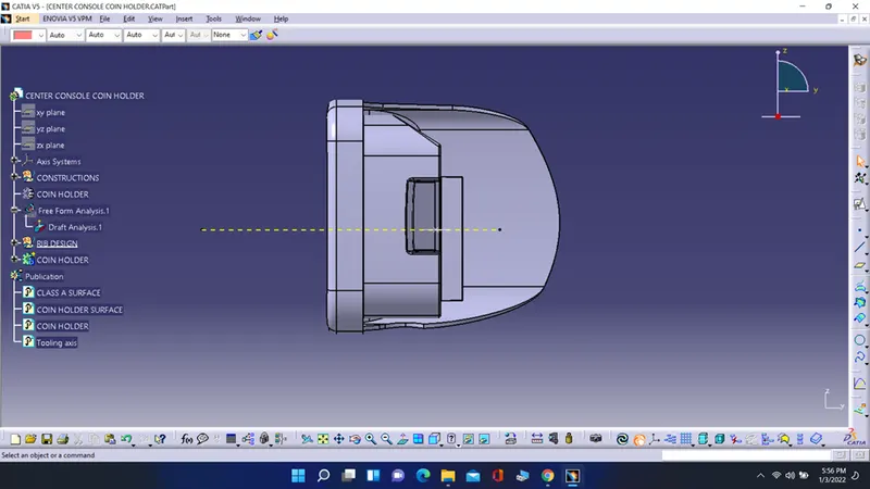
- The next step is to find a tooling axis of the class-A. It means there are so many features and slots are available in the feature because of that there are so many difficulties comes to find a proper tooling axis. Like : - sliders, injector pins and so on.
- Now for tooling axis we can go with bisecting line procedure but in this surface the walls are at 0 degree so we can take a direct line and consider it as tooling axis.
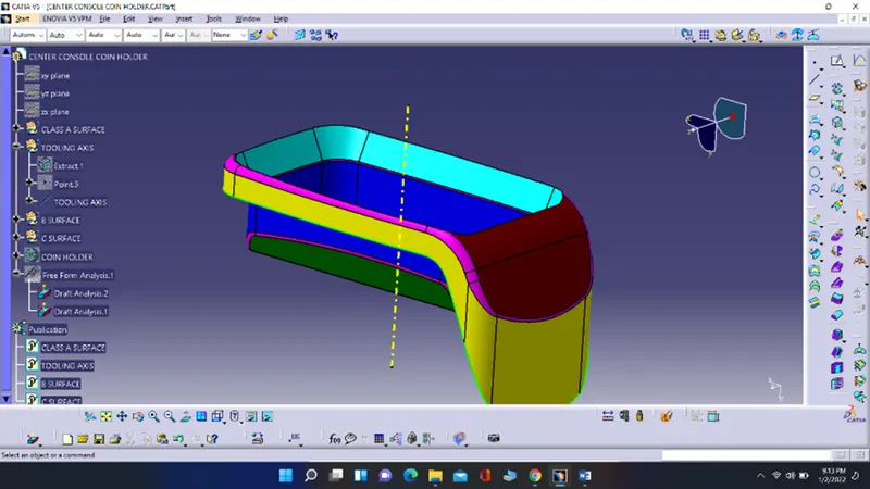
- In next step we have to publication the class-A surface and tooling axis. This task is performed by the tool called as publication.
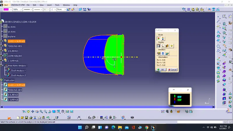
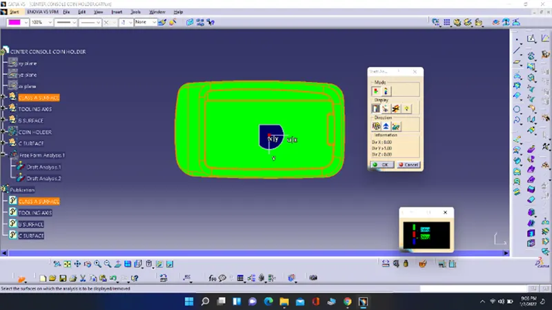
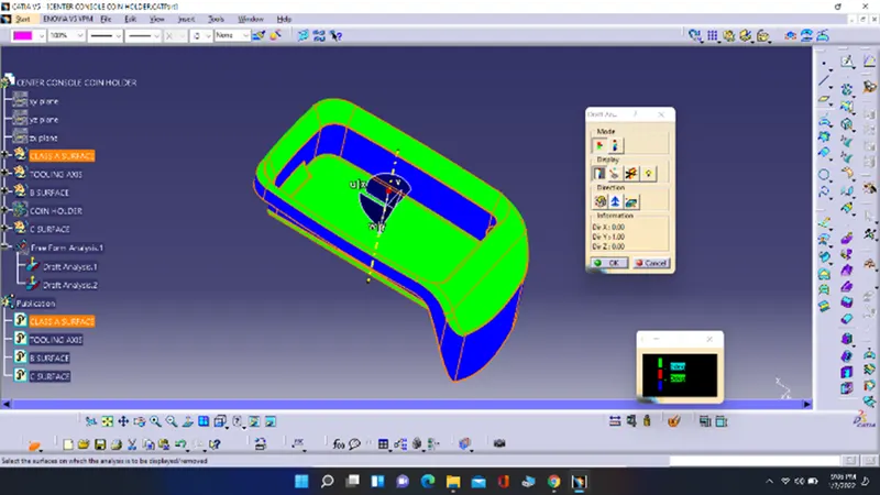
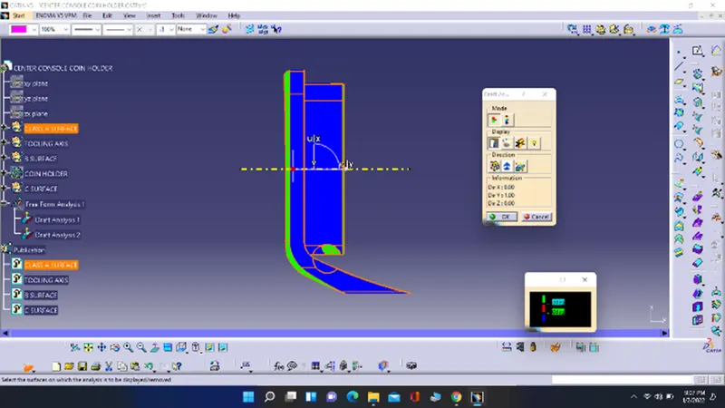
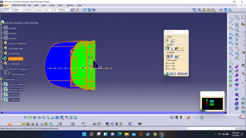
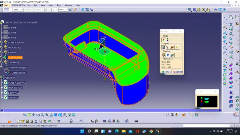
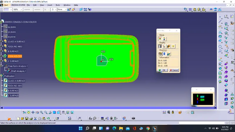
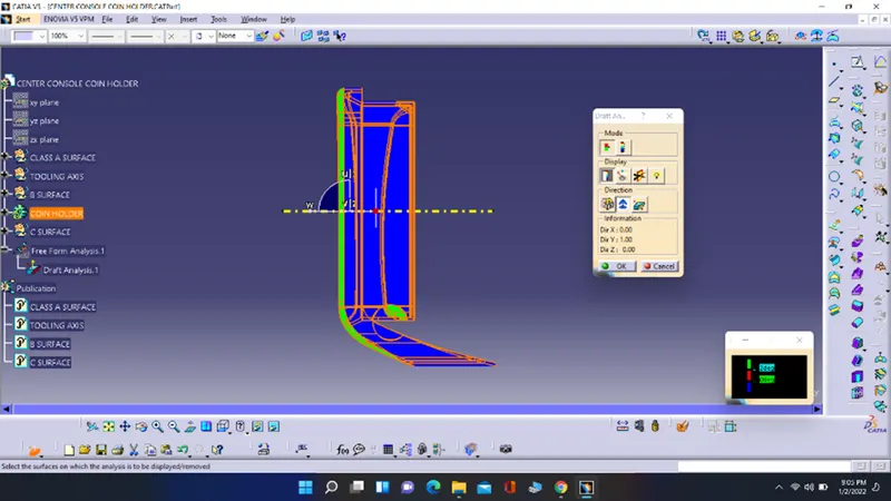
- Now the draft analysis first go to insert go to analysis and feature draft analysis. Now first click the sign of compass then zoom out and pick the red point of the compass and drag it on the class-A surface. Now set it on the tooling axis the W direction is comes on upper side set the compass this way.
- Now you got a red point on the curser click it on the class-A surface then you got the colored surface. And that same color with draft value marked it in the small box on the screen check the draft value from that box. If the draft is proper then the whole class-A surface is becomes a green. And if it is in complete blue then click on the inverse sign which is present in side of compass sign.
2. Creating a solid body using class A,B and C surface: -
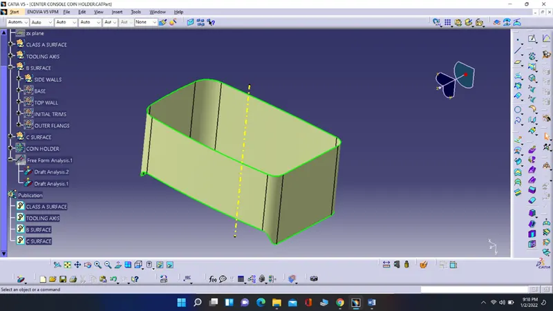
- Now for class B surface first go with the walls. For that extract the surfaces and then extrapolate them and then trim. In last offset them at a given distance. With this I created a walls.
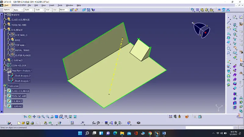
- Now for base surface follow the same procedure which is followed for the walls. Like extract them then extrapolate then trim them with each other and in last offset them with given distance.
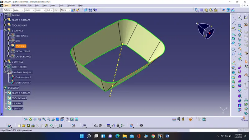
- Now follow the same procedure for the top surfaces and create the surfaces.
- Now trim the walls, base and top surfaces to create a class B surface.
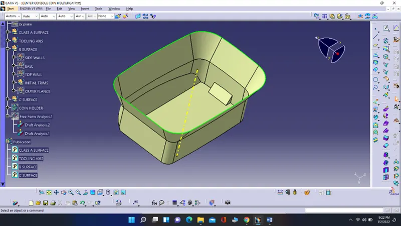
- Now create the outer flanges follow the same procedure and trim then with last trim result.
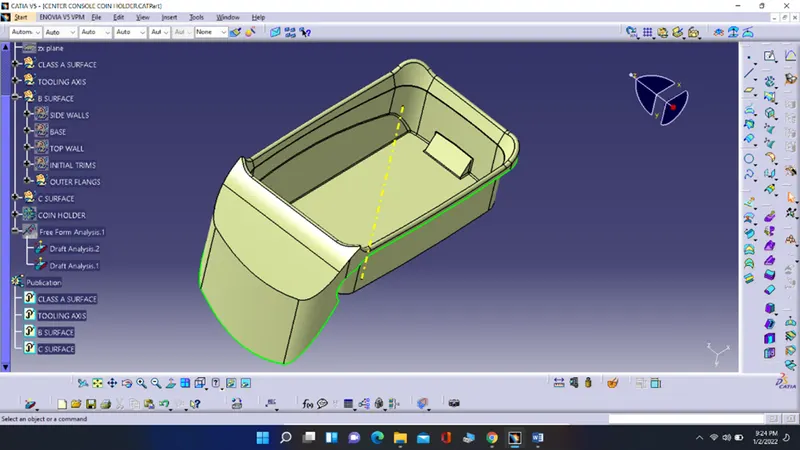
- Now for class C surface first create a boundary of the class A surface and then with help of the swept command use a reference to surface tool and create the swept surface at 90 degree to the class A surface. With same procedure create the swept surface for the hole also.
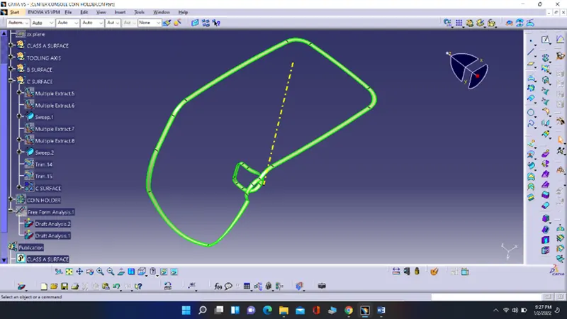
- Now trim the class B and class C surface with each other with proper side to create a final closed surface of the base bracket.
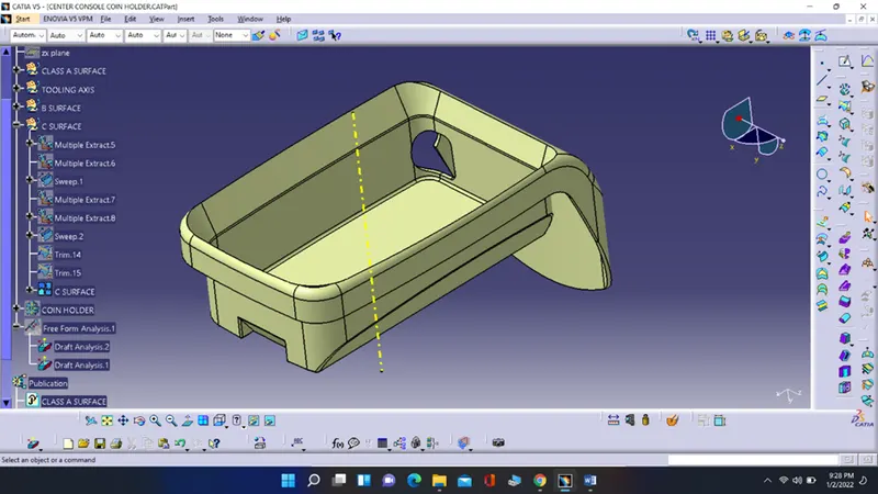
- To create a closed body go into a part body and then use a tool close surface and select the close surface and then enter.
- Now for draft analysis of the part body follow the same procedure which is followed for the class A surface.
3. Draft analysis of the solid body: -
4. Creating a rib on the solid body: -
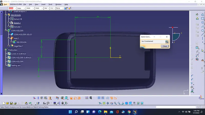
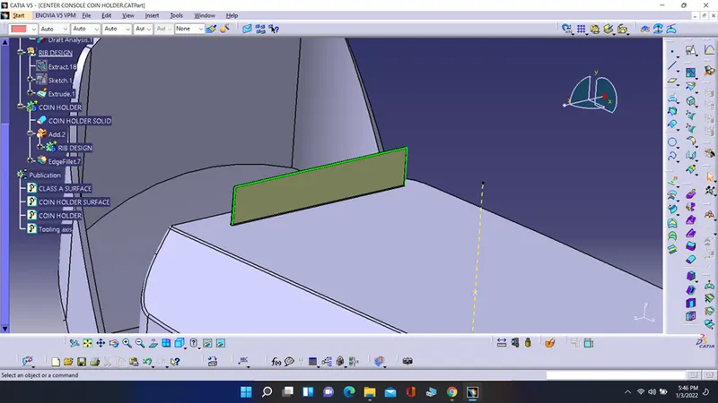
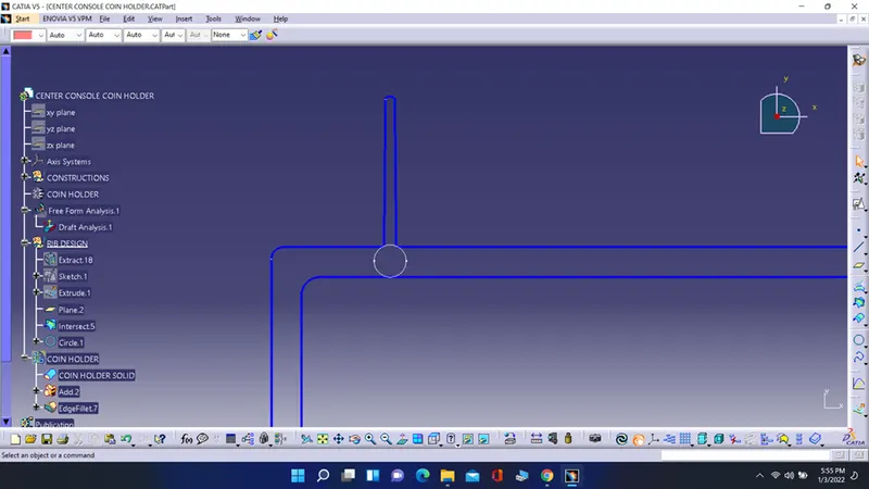
- Now for creating a rib extract the surface on which you want a rib. And then create a line using positioned sketch on that. You simply use extrude surface command and calculate the value using part thickness (height = 5*wall thickness) and give height to extrude.
- Now go to part design and give thickness to that extruded surface using the calculation (W= 0.4 X wall thickness).
- Now give a minimum draft angle to the rib wall which is 0.5 degree.
- And now give the fillet with calculation (r = 0.25 maximum).
- And in last rib root thickness is greater then a wall thickness.