Project 1
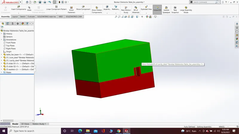
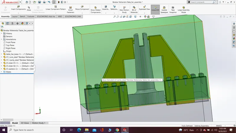
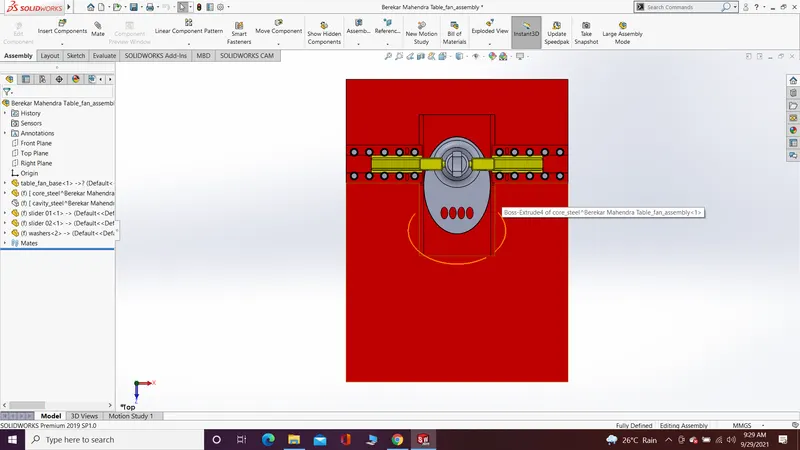
There are the steps which is followed by me to create a mold blocks and sliders for the given geometry:-
- Draft analysis:- For the given geometry first we have to check the draft on the vertical walls so the mold blocks can easily separate from the part. For draft analysis from mold design go through draft analysis command and select the tooling direction the minimum draft required is 0.50 and which wall have minimum draft angle is in green or red colour and which wall not have minimum draft angle is in yellow colour. If there is no draft angle then as mold design engineer we have to in for the part design engineer to provide proper draft.
- Scale:- For mold block design we have to give some scale to geometry to create core and cavity surfaces. For that we have to go through given formula of scale (scale = (material shrinkage of geometry/100) + 1) and assume the material of geometry as ABS (given in challenge report) which have shrinkage of 0.6.
- Parting line:- For parting line we have to choose the edge where the core and cavity surface can easily separate. Sometimes the software can select the right edge but in some case we want to select the edge.
- Shut-off Surface:- we have to closed the open loops where the material is not required in geometry. So there we can use shut-off surface command to close that loops.
- Parting Surface:- For parting surface we have to create a surfaces along with parting line and with use of move copy body command from direct editing just create a copy of parting surface so we can combine one surface with core surface and another one is with cavity surface.
- Core & Cavity surfaces:- With Knit surface command we can combine the core surface and parting surface also cavity and copy of parting surface at same plane. So we can separate the core and cavity block with the help of these surfaces.
- Now open the part file in new assembly file. Create core and cavity part folder in assembly. Now match the origin of assembly and sprue gate location at same point. Also create sliders and washers part file in assembly and save all the files as new part file.
- Now create a sketch with center rectangle where two rectangle is created one to cover entire 3D body of geometry and another one is for 2D body for extra features like sliders and washers. Now with extrude features create a block which cover entire 3D body. With move copy command from direct editing create a same block for the cavity block at same plane.
- Now with cut with surface command cut the blocks using core and cavity surfaces. Give them colour for core block colour is red and for cavity block colour is green.
- Sliders:- First with split command split the slider body from the cavity block. Now give the proper size and wedge (wedge angle 300) to the slider so it can easily move with cavity block. Also remove the material from core block which overlap with slider and from the slider path. Also given a fillet which is required for slider and also on cavity block on respective edges. Save the slider body as new body in parasolid file extension so it is easy to insert the file in slider part file. And also remove slider body from the cavity part file with the help of delete body command from direct editing.
- Create a washers for sliders so it can properly joint with core block and move freely on his path. The dimensions of the washers are standard. Give them a proper place to fix. And remove the material from core and cavity block which overlap with washers. Give extra dimension for relief and in core block use hole wizard command for removing the material.
- Now give a colour to the washers as black and for sliders yellow colour is given. And also some changes is made on slider in last step so to match to cavity block with sliders body i added the part file of sliders and with combine command from direct editing I subtracted the material which is intersect in cavity block.
With these procedure I completed this assignment.