Week 9 - Attachment Feature Creation - Challenge 1
OBJECTIVE
This report is all about to create the Coin Holder Part from the given class A surface.Then create Tooling axis by bisecting method & perform Draft analysis on it and then to design RIB for the part.
DETAILED REPORT
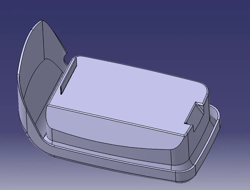
To start the work with we need the class A of the coin holder as shows in Fig-1
- Before starting the work we need to check the proper boundary walls that we are going to work upon.To check that we need to see which boundary we are going to start with.As fig-2 shows there are 2 out lines.As the small one is just there for the hole in the coin holder so we consider the bigger curve shown for designing the part .
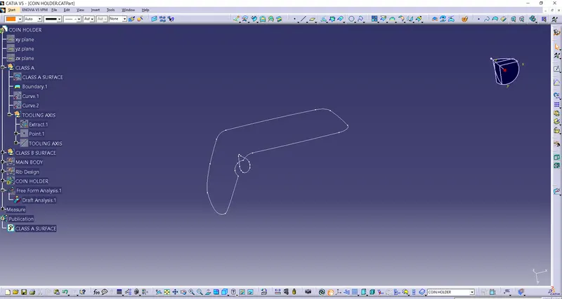
(FIG-2)
Now As the boundary selection concluded it leads us to another task that is selecting Tooling Direction.
- Below Fig-3 Shows the Isometric view of the coin holder part as we have to select the tooling direction for the part we have to consider the most suitable,cost effective direction for manufacturing of the part.Her in this case if we go for X&Z direction though we can manufacture the part but with many difficulties as it has few areas where there is no possiblities of the moving of the core & cavity block. So we have to select the Y-direction for the manufacturing of the part.
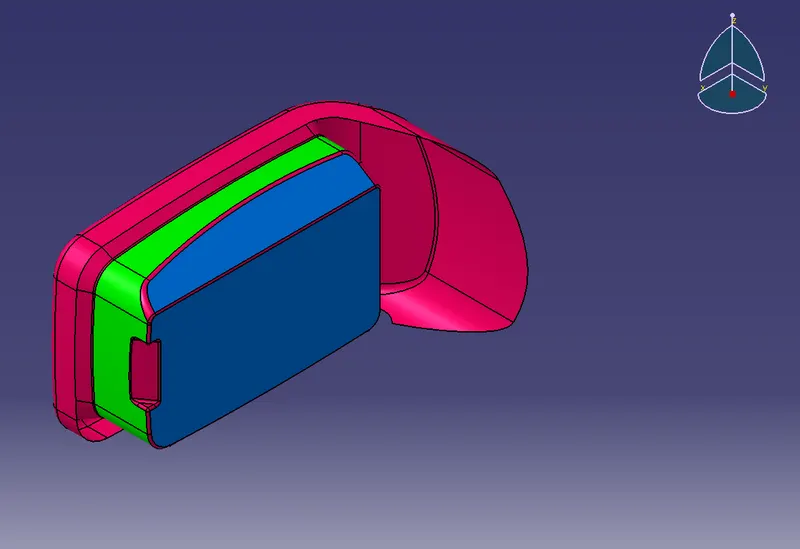
(FIG-3)
- Now as the direction confirmed we have to make the TOOLING AXIS for manufacturing the part.
- To create the tooling axis we need the normal plane to the Y-dir.(Base of the Coin holder)
- Now we have to extract the base & create a point on the base,That point will create at the middle of the base by default.
- Then create line with the help of Point-direction option & will result the Tooling Axis.(
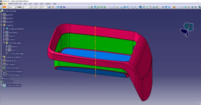
(FIG-4)
This above figure shows Class A & the Tooling axis.
Now we have to perform the Draft Analysis on this Tooling Axis.
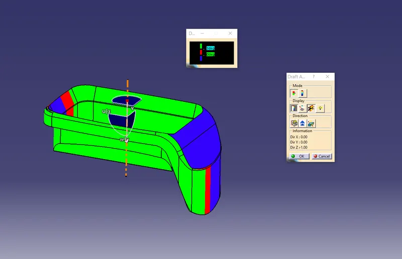
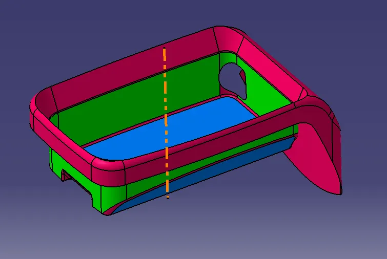
This Figure shows the draft analysis for the Coin holder.Now with this colours we can figure it out that the green area can be cleared easily with present tooling axis but for other colour we need to do some extra arrengment.
Now as the Draft analysis completed we can further proceed to create the class-B for the part.
To do that we need to extract the full part into small small entities as shown in below picture.
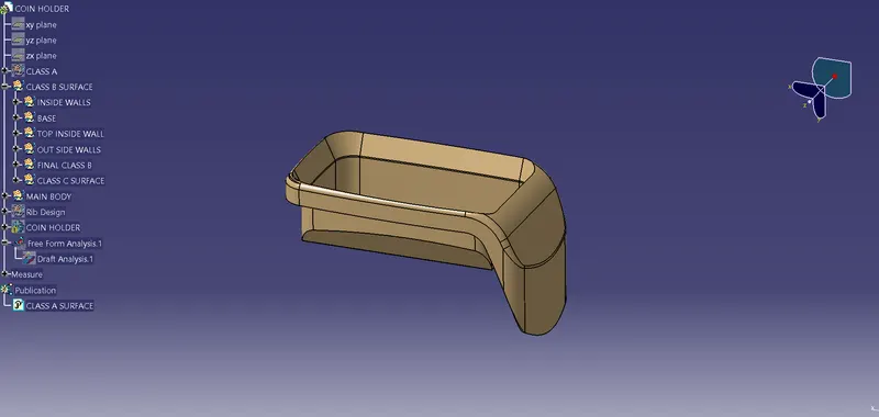
As per the tree structure we break the whole part into some segments(inside walls,base,top inside walls,out side walls).
- To create this we need to Extract the respected sides & offset it to 2.5 mm inside from the class A surface.
- Then we have to create the Class C surface(the limit of the Class B surface is called the class C surface.)
Now the part is ready & we have to make the created part in to solid body for that we need to choose the CLOSE SURFACE option in part modeling work bench.
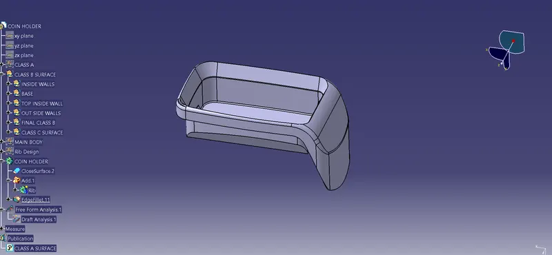
(This is figure for the close surface body)
Now We have to design the Rib for the part of 2.5mm thickess
for designing the rib we need to see the following thimgs
- DRAFT(0.5 degree)
- RIB THICKNESS (0.4*t)
- RIB FILLET RADIUS
- RIB HEIGHT(5*t)
So for our part the values will be as follows
DRAFT-0.5
RIIB THICKNESS-0.4*2.5=1
RIB FILLET RADIUS-0.25MM
RIB HEIGHT-5*2.5=12.5MM
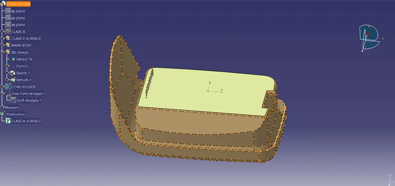
To design the rib we need to extract the base then create a line on that base.then Extrude the line upto desired height.
Then thicken that surface to 1mm thickness and apply the draft & radius into it.Then add the part into main body & we will get the desired Output.