Week 9 - Attachment Feature Creation - Challenge 1
AIM - To create the rib for the Centre console coin holder considering the design rules.
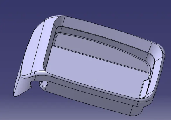
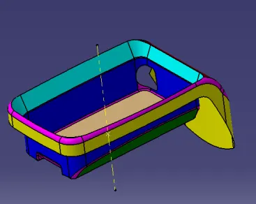
PROCEDURE - The coin holder part is shown below:
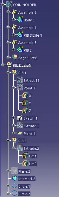
The tree structure of the component is shown below:
Tooling axis - The tooling axis is defined as the direction in which the mold opens or core and cavity opens and closes. The selection of the correct tooling axis is
important to ensure the component is taken out perfectly and also the cost of the component should be less.
I will start by inserting a geometrical set and naming it as a tooling direction. For creating the tooling axis I will analyze the model and see from which direction i
can see the whole model. so here the direction i have chosen for the tooling axis is along the y direction because along the y-direction the whole model is visible
properly.
For creating the tooling axis first i will extract the base from the class A surface. And will create a point on the center of that base. Then i will insert an axis system
on that point. since i have chosen the Y direction as my tooling axis i have to make sure that the tool should clear in both x and z-direction. so for x-direction, i will
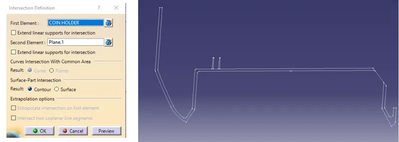
not create an intersection because there are no surfaces that would cause a problem during ejection. But for z-direction, i will create an intersect. The intersection
parameters are shown below:
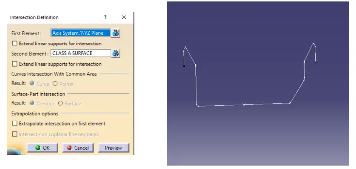
Here in the above fig., u can see that there are some lines which would not be perpendicular to the tooling axis but it will not cause any problem because most of
the lines are drafted outwards so it will not intersect with the tooling axis. so for creating the tooling I will just simply create one line along the y-direction which
will be my tooling axis. The tooling axis is shown below:
Now I will design the Ribs
Ribs - Ribs are a feature in plastic injection molded parts. They are thin extensions that run perpendicular to a wall or plane. They are commonly used to provide
additional support and strength to a part. Thickness and location are essential to rib design.
There are some rules which we have to keep in mind while designing the ribs and those rules are:
1) Rib thickness - Ribs should be designed to be 40 percent of the nominal wall thickness. Thinner does not provide much structure and may be hard to fill. Thicker
ribs are tempting, but they can begin to introduce sinks on the cosmetic surface.
2) Rib height - The Rib height should be greater than or equal to 5 times the wall thickness.
3) Rib spacing - Increase the number of ribs rather than their height in order to increase stiffness. Ribs should be spaced a minimum of two times the nominal wall
thickness apart from one another. or it can be done in the ratio as well. The ratio will be of a height to width ratio.
4) Minimum thickness at the tip - We have to ensure that the minimum thickness at the rib tip must be 0.75 mm
5) Draft - A minimum 0.5-degree draft will ensure that they release from the tool during molding.
6) Rib coring - Core thick ribs from the back or below to create a blank area and thinner rib walls. This will help mitigate cosmetic sinks.
7) Radii - The fillets provided in the ribs should be in the range of 0.25mm to 0.5mm. Generally, it is recommended to give 0.25mm fillets.
So here now I will create the ribs according to the above-mentioned rules.
so in that coin holder part, I will create the ribs on the backsides because that side requires some strength and hence I will create the ribs on the B side surface.
First, I will extract the back surface and create a sketch on that side. The extract and sketch are shown below:
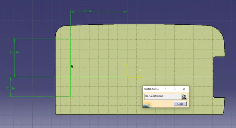
After creating the sketch I will extrude the sketch that is a line along the tooling direction. The extrude parameters are shown below
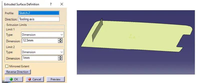
Here u can see that I have extruded the sketch to 12.5 mm considering the design rule for rib height that is 5 times the wall thickness. here the thickness of the part
is 2.5mm. so 2.5 multiplied with 5 will give the Rib height.
After extruding I will insert a body and I will thick the extrude I have created. The thick surface is shown below:
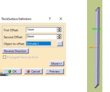
The thickness here I have given is 1 mm to ensure that I follow the thickness rule which is 40 percent of the wall thickness. so when I multiply 0.4 with the wall
thickness that is 2.5 I get 1mm.
After thickening the surface I will provide the draft. So I will provide 0.5 degrees of the draft because 0.5 degrees draft is applicable for ribs. The draft is shown
below:
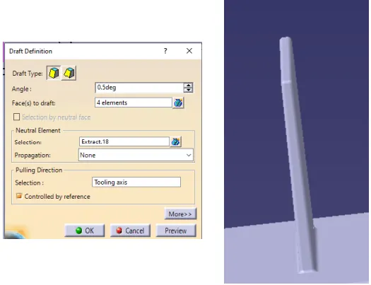
After providing the draft I will add this body to the main body and then provide the fillets to the ribs. The fillet radii should be 0.25mm keeping in mind the design
rules for ribs. The fillets are shown below:
But before providing the fillets I will check for the top edge thickness it should be above 0.75mm in my case it was 0.786 mm which is correct
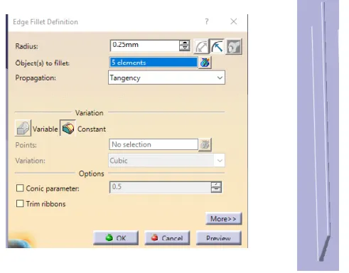
After providing the fillets I will create one more rib but keeping in mind the spacing rule for ribs. so I will create one more sketch. The sketch is shown below
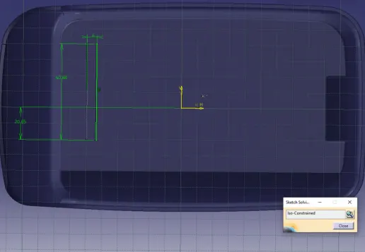
Here the spacing will be in the ratio of 3 is to 1.
Then again I will follow the same procedures as I did for the first rib. I will extrude the sketch to 12.5 mm and then thicken it to 1 mm The process is shown below:
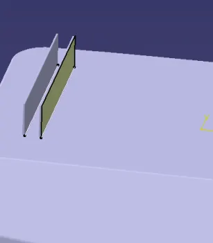
Then i will provide the 0.5 degrees of draft and 0.25 mm radii fillets to the ribs. The second rib is shown below
Then I will two tangent circles and measure that circle. The circle parameters are shown below:
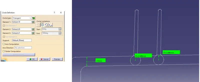
so here I have ensured that the rib root thickness is greater than the part thickness. Now i have designed the rib for coin holder following all the design rules and
next i will do the draft analysis on the model.
Draft analysis - Draft analysis is a technique to analyze whether the component created is manufacturable or not based on the draft conditions applied. So here i
will provide the direction in which the component should be ejected to get the easy removal. My direction will be the tooling axis that i have created.
The minimum draft value for the Automotive plastic component is 3 degrees and those for the texture faces 7 degrees od draft is suitable. The draft is provided to
the component for easy removal from the mold in the case of a plastic component.
So here i will change the customize view parameters and will select the material mode.\
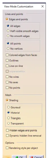
Then I will go insert and select the analysis and in the analysis, i will select the draft analysis. The draft analysis block is shown below
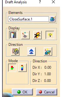
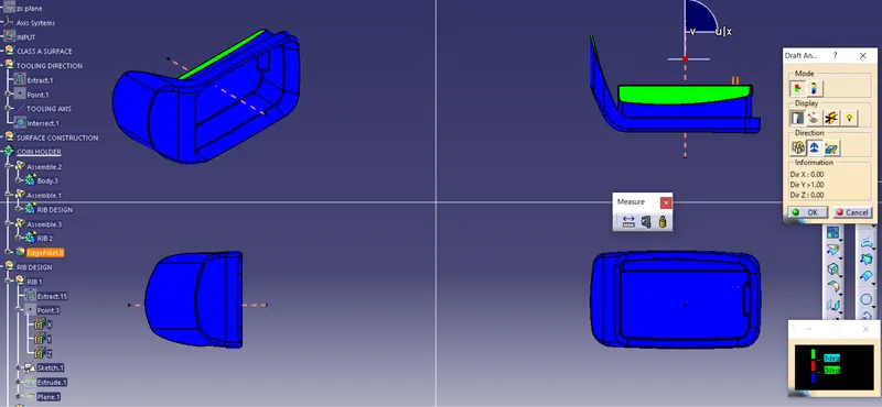
In the above fig. under the display, section select the color scale and turn on the light effect for proper visualization. then under the direction section, i will click on
the compass and will drag the compass from vehicle zero to my tooling axis. and then i will click on the lock feature and will select the class a surface. The result is
shown below: